Hub posture detection method and apparatus

a technology of posture detection and apparatus, applied in the direction of process control, process and machine control, instruments, etc., can solve the problems of poor efficiency of wheel mounting, long processing time of images taken by these cameras, complicated apparatus, etc., and achieve the effect of enhancing productivity and improving detection accuracy

Inactive Publication Date: 2011-12-27
HONDA MOTOR CO LTD
View PDF6 Cites 16 Cited by
  • Summary
  • Abstract
  • Description
  • Claims
  • Application Information

AI Technical Summary

Benefits of technology

[0007]In view of the foregoing prior art problems, it is an object of the present invention to provide an improved hub posture detection technique which only requires an apparatus of a simple construction, and which can detect a hub posture with an enhanced detecting accuracy and thereby achieve an enhanced productivity.
[0009]According to the hub posture detecting method of the present invention, distances from the reference position to the first and second horizontally-elongated rectangular areas of the hub surface are measured by distance meters, and then, center coordinates of the hub bolts and hub, an inclination angle of the hub and orientations of the hub bolts are calculated. In this way, the method of the present invention can achieve an enhanced hub posture detecting accuracy. Namely, the method of the present invention uses distance meters, such as laser sensors, in place of cameras that present the problem that processing images taken by the cameras tends to be time consuming.
[0011]According to the hub posture detecting apparatus of the present invention, which comprises the two distance meters for measuring distances to the first and second horizontally-elongated rectangular areas and the control device. Thus, the hub posture detecting apparatus can be simple in construction. In addition, because distances to only two areas, i.e. only the first and second horizontally-elongated rectangular areas, of the hub surface have to be measured, the present invention can reduce the number of necessary distance information processing steps and thus achieve an enhanced wheel-mounting efficacy and productivity.

Problems solved by technology

First, because the touch plate 110 is necessary, the apparatus is complicated in construction.
Third, with the disclosed apparatus, where the first and second visual cameras are employed, processing of images taken by these cameras would take a long time, which results in a poor wheel mounting efficiency and hence a poor productivity of vehicles.

Method used


Image

  • Hub posture detection method and apparatus
  • Hub posture detection method and apparatus
  • Hub posture detection method and apparatus

Examples


Embodiment Construction

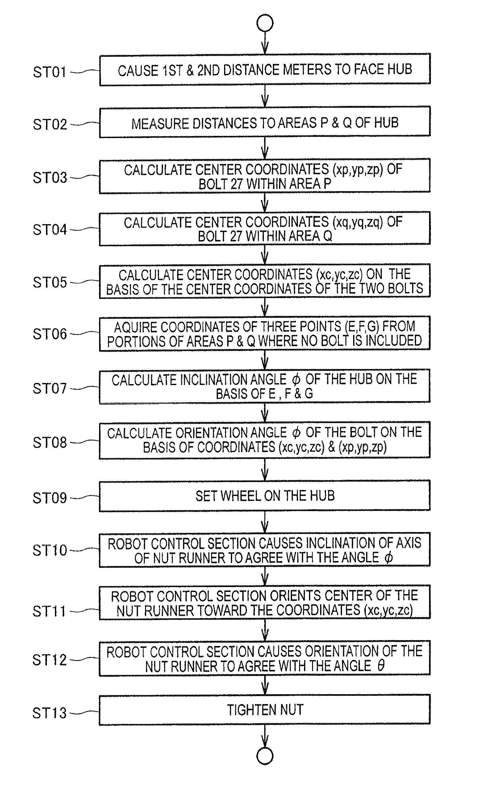
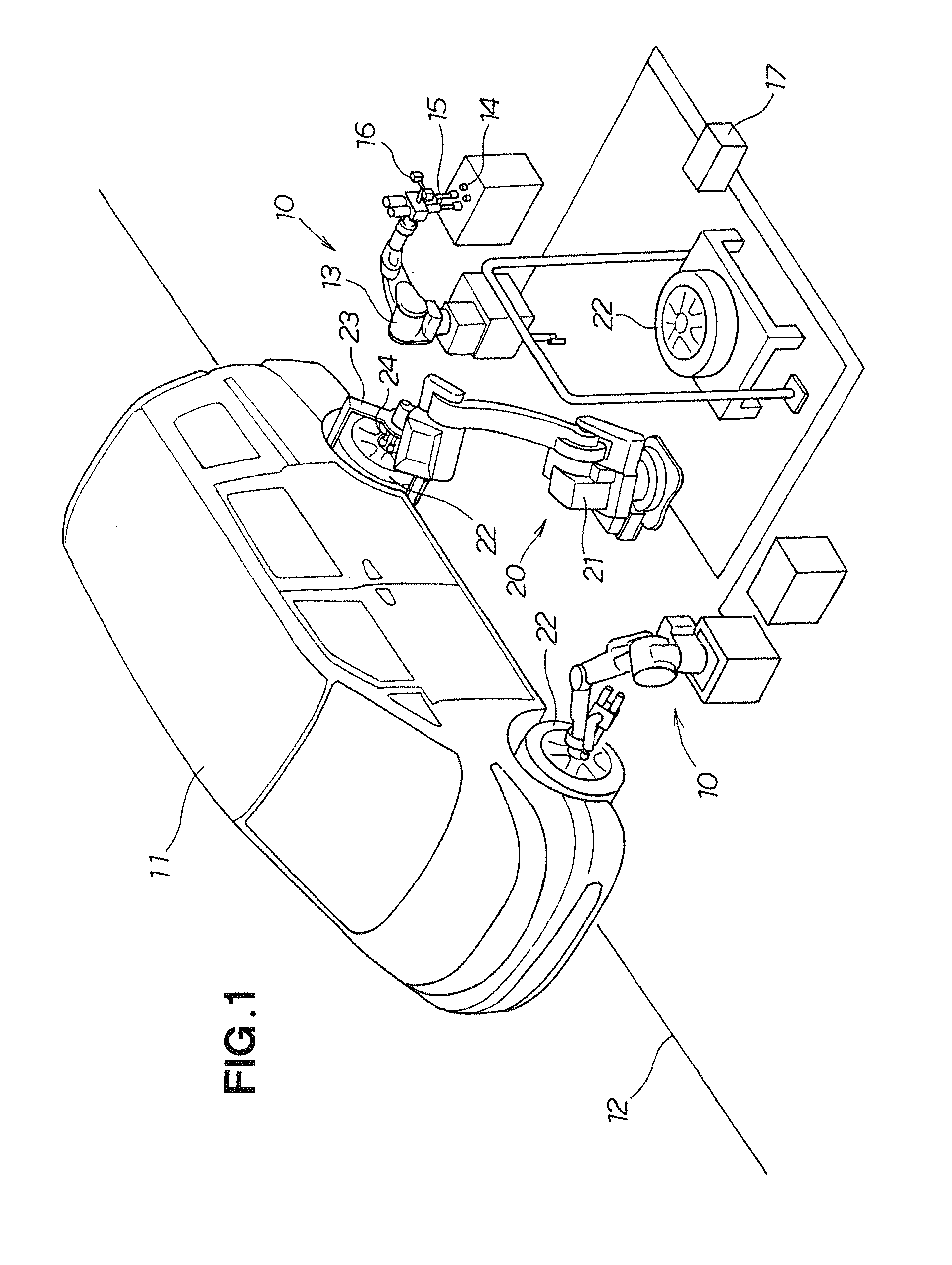
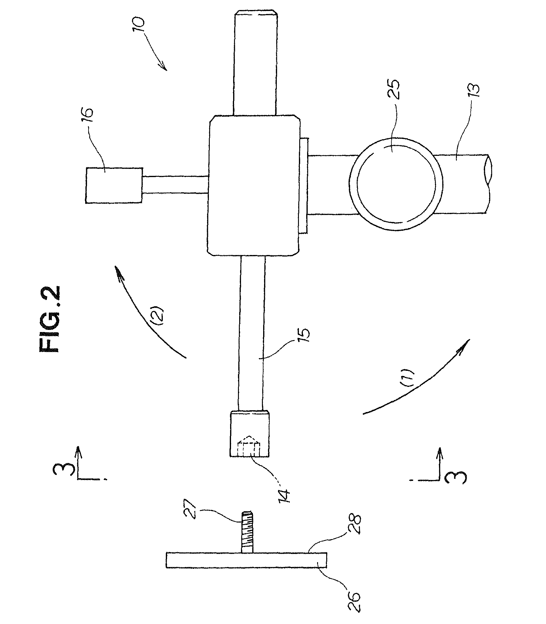
[0028]Reference is now made to FIG. 1 diagrammatically showing a general setup of an embodiment of a hub posture detection apparatus 10 of the present invention. The hub posture detection apparatus 10 includes a robot 13 provided for movement along a vehicle conveyance line 12 for conveying a vehicle 11, a nut runner 15 provided on a distal end portion of the robotb 13 for tightening a nut 14, a measurement section 16 provided on the distal end portion of the robotb 13 for measuring distances to a hub surface 28, and a robot control section 17 for controlling behavior of the robot 13.

[0029]Once the hub posture detection apparatus 10 detects a posture of the hub (i.e., inclination and center of the hub and orientations of hub bolts), a wheel supply apparatus 20 mounts a wheel 22 on the hub and the nut runner 24 tightens the nut on the basis the detected hub posture. In this way, the wheel can be fixed to the hub.

[0030]The wheel supply apparatus 20 includes, for example, a robot 21, a...


PUM

PropertyMeasurementUnit
speedaaaaaaaaaa
lengthaaaaaaaaaa
lengthaaaaaaaaaa

Abstract

Distance meters measure distances from a reference position to a first area including an upper pitch circle portion and a second area including a lower pitch circle portion. Center coordinates of the hub is calculated based on respective center coordinates of two hub bolts included within the first and second areas. Coordinates of three points defining apexes of a triangle are acquired. Inclination angle of the hub relative to a vertical plane is calculated based on the coordinates of the three points, and an orientation of each of the hub bolts is calculated based on the center coordinates of the hub and the center coordinates of the hub bolt.

Description

FIELD OF THE INVENTION[0001]The present invention relates to a technique for detecting an inclination and center of a hub and orientations of hub bolts of a vehicle at the time of mounting a wheel on the hub.BACKGROUND OF THE INVENTION[0002]In assembly of mass-produced vehicles, a technique for automatically mounting a wheel on a vehicular hub has been in practical use, one example of which is disclosed in Japanese Patent Application Laid-Open Publication No. HEI-06-190661.[0003]FIG. 13 hereof is a view explanatory of a fundamental construction of a wheel mounting apparatus disclosed in the HEI-06-190661 publication. The wheel mounting apparatus 101 includes a robot 102, a first visual camera 103, a second visual camera 104, a laser sensor 105, a nut runner 106, a wheel clamp 107, a cylinder 108, a ball joint 109 connected to the cylinder 108, and a touch plate 110 connected to the ball joint 109. Reference numeral 111 indicates a wheel, 112 a hub, 113 hub bolt, and 114 a nut.[0004]...

Claims


Application Information

Patent Timeline
Patent Type & Authority Patents(United States)
IPC IPC(8): G06F19/00
CPCB23P19/10B25J9/1687B25J9/1697B62D65/12G01B21/26Y10T29/49481G05B2219/37608G05B2219/45021Y10T29/49948
Inventor KONDO, TOSHIYUKISHIBAYAMA, TAKAO
Owner HONDA MOTOR CO LTD
Why Eureka
Try Eureka