Device and a method for moving a jet member

a technology for jet members and devices, applied in the direction of ratio control, fluid pressure control, transportation items, etc., can solve the problems of cable cables catching or touching anything, and achieve the effect of reducing the risk of operation disturbances

Active Publication Date: 2011-12-27
AQUAJET SYST HLDG
View PDF6 Cites 8 Cited by
  • Summary
  • Abstract
  • Description
  • Claims
  • Application Information

AI Technical Summary

Benefits of technology

[0005]The object of the present invention is to provide a device and a method of the type defined in the introduction, which makes it possible to reduce the risk of the operation disturbances mentioned above of such devices and methods already known.
[0007]By arranging such a mechanical resistance to continued movement of the carriage and sensing said parameter of the hydraulic liquid it gets possible to manage without any sensor on the carriage if desired and by that manage without said cabling responsible for the main part of the operation disturbances in the electric system of such devices already known. The means for detecting that the carriage has reached a said extreme position gets by that very robust and the entire device may be made more robust than before. A measuring of such a parameter depending upon the flow of the hydraulic liquid is also very easy to realize.
[0009]According to another embodiment of the invention said sensing member is adapted to sense the pressure of the hydraulic liquid in said hydraulic circuit between a hydraulic pump and a hydraulic motor arranged at the carriage. This constitutes a reliable and easy way to detect that the carriage has arrived to a position in which said member forms a mechanical resistance to continued movement of the carriage. The restriction usually arranged in the hydraulic circuit between the hydraulic pump and the hydraulic motor is then utilized by designing the sensing member to measure the pressure of the hydraulic liquid downstream of the restriction. When there is no substantial resistance to the movement of the carriage a pressure fall will result across the restriction, so that a considerably lower pressure than the system pressure will be sensed by the sensing member, while this pressure will be increased for being the same as the system pressure in case the mechanical resistance would completely stop the carriage from moving further and by that stop the flow of hydraulic liquid in the hydraulic circuit.
[0010]According to an embodiment of the invention the mechanical resistance member is formed by a mechanical stop member arranged along the guide and to define said extreme position by forming an obstacle to and being hit by the carriage or a member connected thereto. This constitutes an extremely simple and reliable solution to the problem to be solved by the invention. When the carriage will hit the stop member it will stop in a well defined extreme position, since it may not move any longer, and this will influence the flow in the hydraulic circuit, so that the control unit through the sensing member gets information thereabout and may control the turning of the carriage on basis of said information. The control unit may then when receiving this information for instance start a pivoting of the jet member with respect to the carriage and / or a stepping forward of the entire vehicle before the hydraulic drive arrangement is controlled to start to move the carriage towards the other extreme position.
[0011]According to another embodiment of the invention said stop member is arranged movable and securable in different positions along the guide for determining the position for said extreme position and by that the working width of the jet member. Such a stop member is easy to move and secure in different positions so as to in an extremely easy way change the working width of the jet member while maintaining a completely reliable detection of the extreme positions for the carriage through the members adapted to sense said parameter of the hydraulic liquid.
[0017]According to another embodiment of the invention the device further comprises a second sensing member arranged on said carriage and marks arranged along said guide, the second sensing member is designed to detect that the carriage reaches said marks and send information thereabout to the control unit, and the control unit is adapted to enable changing between by on one hand letting said means determine the position of said extreme positions and on the other letting said marks determine the position of said extreme positions. It gets by this possible in some operation situations to use a first sensing member and determine said extreme positions through the mechanical resistance member and measurement in the hydraulic circuit and in other situations determine the extreme position through said sensing members of the type discussed in the introduction arranged on the carriage. It is also possible to use that type of extreme position determination and if the risks for disturbances in any particular working situation are judged to be high this sensing member may be switched off and the sensing through the mechanical resistance member may be used. Another possibility through the existence of the two types of sensing members is to enable shifting between different working widths without having to carry out other actions than shifting between the sensing members for determining the extreme positions. This may be an advantage if the vehicle is difficult to access, for instance by the fact that the carriage with the jet member is working on a high level along any wall or in a ceiling in a tunnel or the like.

Problems solved by technology

90% of all operations disturbances in the electric system of devices of this type already known emanates from this cabling outside the cabinet to the sensor on the carriage, since the environment in which the cabling is running is very tough with concrete pieces and the like flying around, at the same time as there is a risk that the cables may catch or touch anything when rotating the assembly to which the jet member with carriage belong during the material removing treatment of material layers of different types of objects.

Method used


Image

  • Device and a method for moving a jet member
  • Device and a method for moving a jet member
  • Device and a method for moving a jet member

Examples


Embodiment Construction

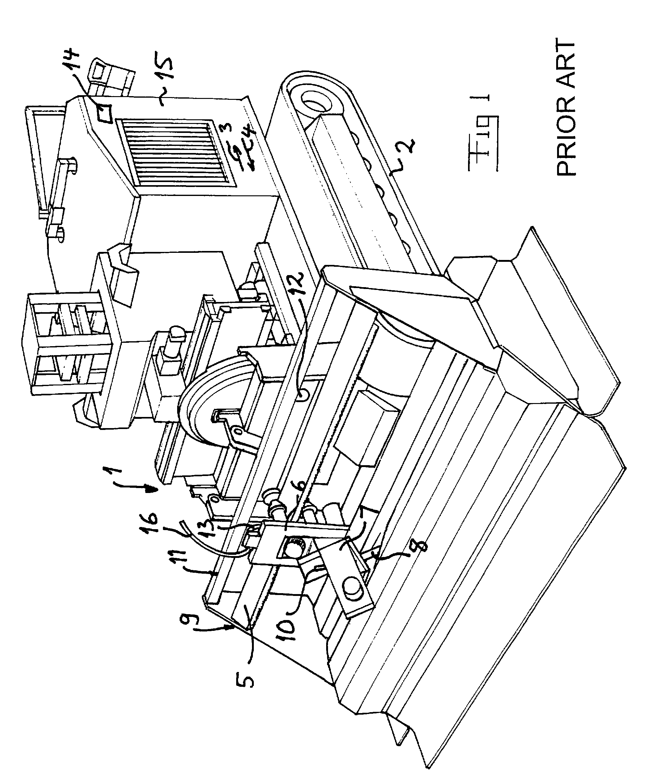
[0028]A device according to prior art of the type to which the present invention belongs may as illustrated in FIG. 1 be arranged on a mobile unit generally designated by 1. This has the character of a vehicle movable on a bedding, for example a layer of concrete, which is to be treated. The vehicle is here indicated to be of crawler-type with two driving tracks 2. The vehicle is movable in opposite directions as also indicated by the arrows 3 and 4.

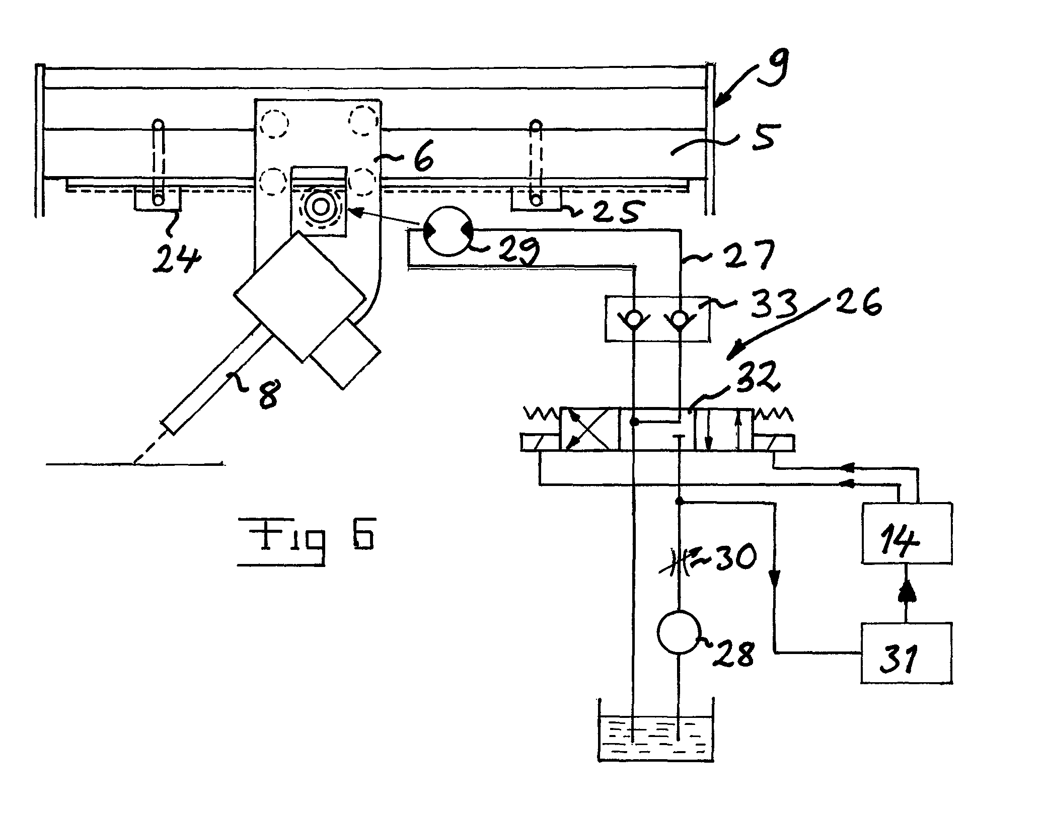
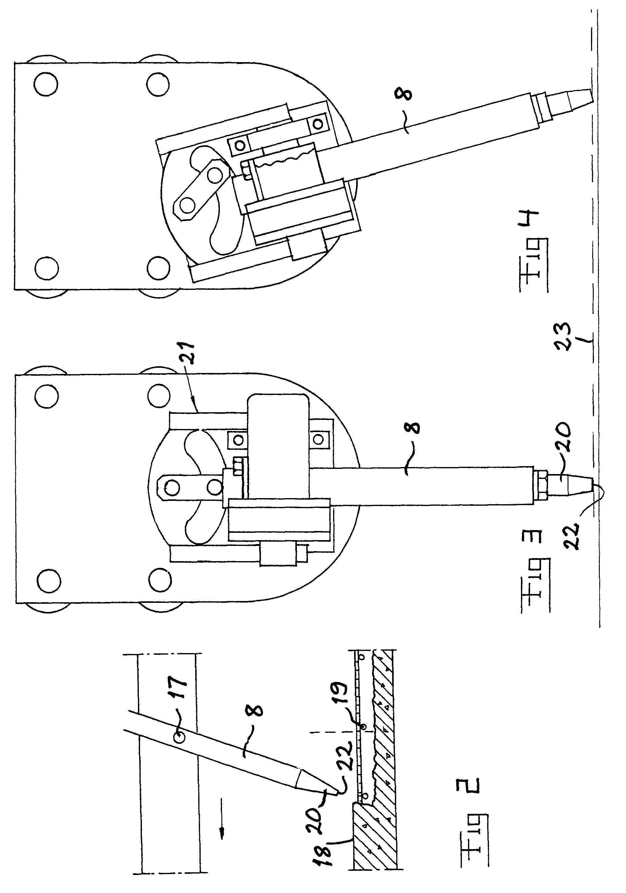
[0029]An elongated guide 5 is arranged on the vehicle 1 and a carriage movable to and fro along this guide, which is generally designated by 6. A base portion 7 constitutes a part of the carriage 6. A tube-type jet member 8 is arranged on the base portion 7 for directing a high pressure jet of liquid against the bedding. The guide 5 in operation is intended to make an angle to the moving directions 3, 4 of the vehicle and preferably to extend transversely thereto. The guide 5, which may have the character of one or more beams, is in the ...


PUM


Abstract

A device for moving a jet member on a carriage (6) between two selectable extreme positions along a guide (5) has means for detecting that the carriage has reached a selectable extreme position, said means comprising members (24, 25) adapted to form a mechanical resistance against continued movement of the carriage so as to influence the flow of hydraulic liquid in an hydraulic circuit (27) of a hydraulic drive arrangement for moving the carriage. Members (31) are arranged to sense a parameter of the hydraulic liquid, the magnitude of which is depending upon the flow of hydraulic liquid in the hydraulic circuit, and send information about the magnitude of this parameter to a control unit (14) adapted to control the turning of the carriage on the basis of this information.

Description

FIELD OF THE INVENTION AND PRIOR ART[0001]The present invention relates to a device for moving a jet member, so as to through a high pressure jet of liquid obtain material removing treatment of a material layer as well as a method for moving a jet member according to the preambles of the appended independent claims 1 and 15.[0002]The layer to be treated consists preferably of concrete, but it may also consist of another material. Primarily, the treatment is intended to have the purpose to remove weakened material from the layer. It may then be a question of removing weakened concrete from concrete layers on roads, bridges and a variety of building structures, whereupon the removed concrete may be replaced by new concrete. Preferably, the high pressure liquid consists of water.[0003]A device and a method of the type defined in the introduction are for example described in our European patent 0 544 775. Such a device has means adapted to detect that the carriage has reached a selectab...

Claims


Application Information

Patent Timeline
Patent Type & Authority Patents(United States)
IPC IPC(8): G05D1/02B60P3/30E01C23/12
CPCB05B13/0415B24C3/04E04G23/08E04G23/02E01C23/128Y10T137/6855Y10T137/6903B26F3/004E01C23/124
Inventor HILMERSSON, RONNIE
Owner AQUAJET SYST HLDG
Why Eureka
Try Eureka