Turbine cooling air from a centrifugal compressor

a technology of centrifugal compressor and turbine cooling air, which is applied in the direction of machines/engines, stators, liquid fuel engines, etc., can solve the problems of engine power and useable blade life reduction, engine shutdown, and engine life and mechanical integrity

Active Publication Date: 2012-01-03
GENERAL ELECTRIC CO
View PDF12 Cites 60 Cited by
  • Summary
  • Abstract
  • Description
  • Claims
  • Application Information

AI Technical Summary

Problems solved by technology

Failure to adequately cool a turbine disk and its blading, for example, by providing cooling air deficient in supply pressure, volumetric flow rate or temperature margin, may be detrimental to the life and mechanical integrity of the turbine.
Depending on the nature and extent of the cooling deficiency, the impact on engine operation may range from relatively benign blade tip distress, resulting in a reduction in engine power and useable blade life, to a rupture of a turbine disk, resulting in an unscheduled engine shutdown.
Since turbine cooling air is typically drawn from one or more stages of the compressor and channelled by various means such as pipes, ducts and internal passageways to the desired components, such air is not available to be mixed with fuel, ignited in the combustor and undergo work extraction in the primary gas flowpath of the turbine.

Method used


Image

  • Turbine cooling air from a centrifugal compressor
  • Turbine cooling air from a centrifugal compressor
  • Turbine cooling air from a centrifugal compressor

Examples


Embodiment Construction

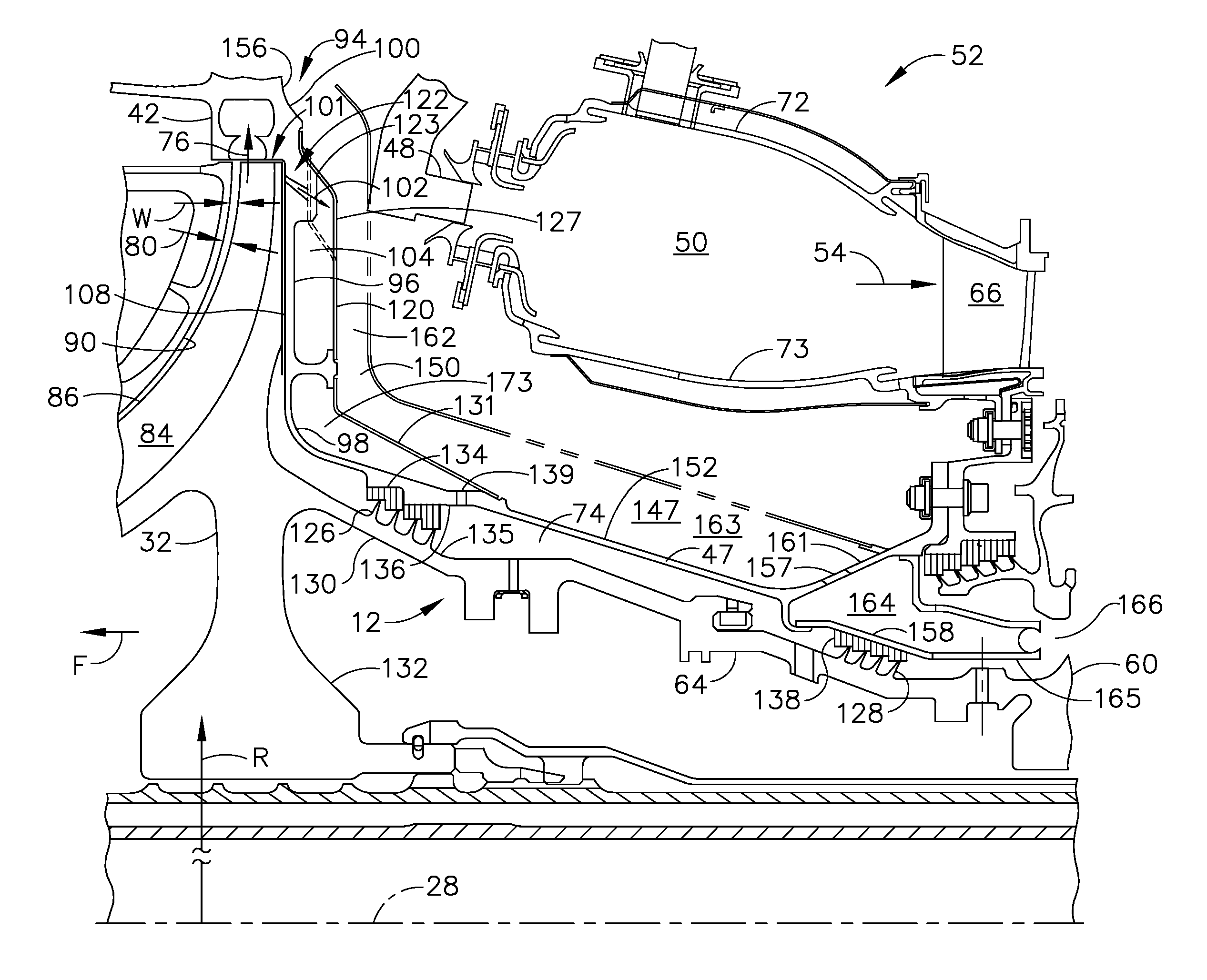
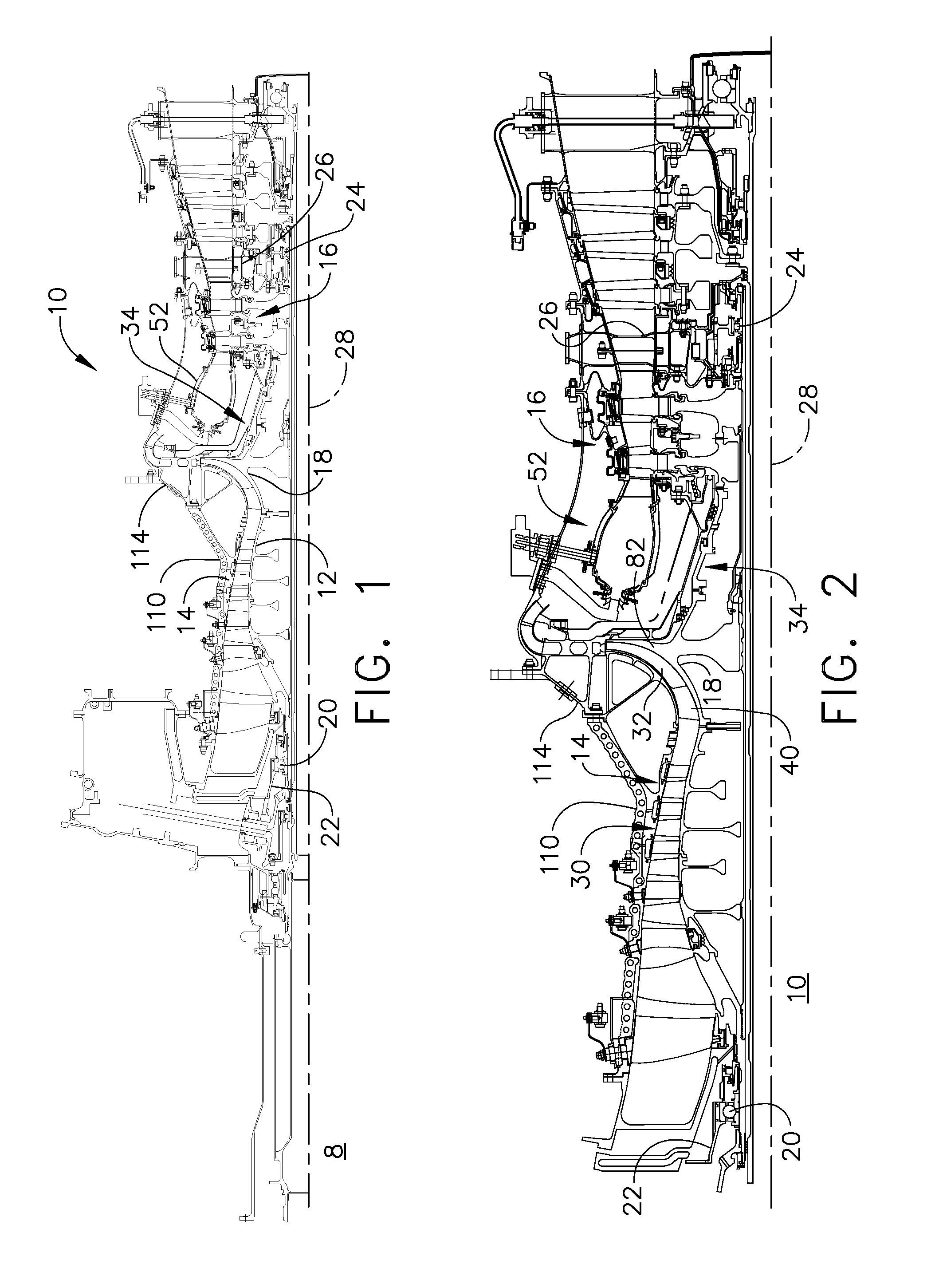
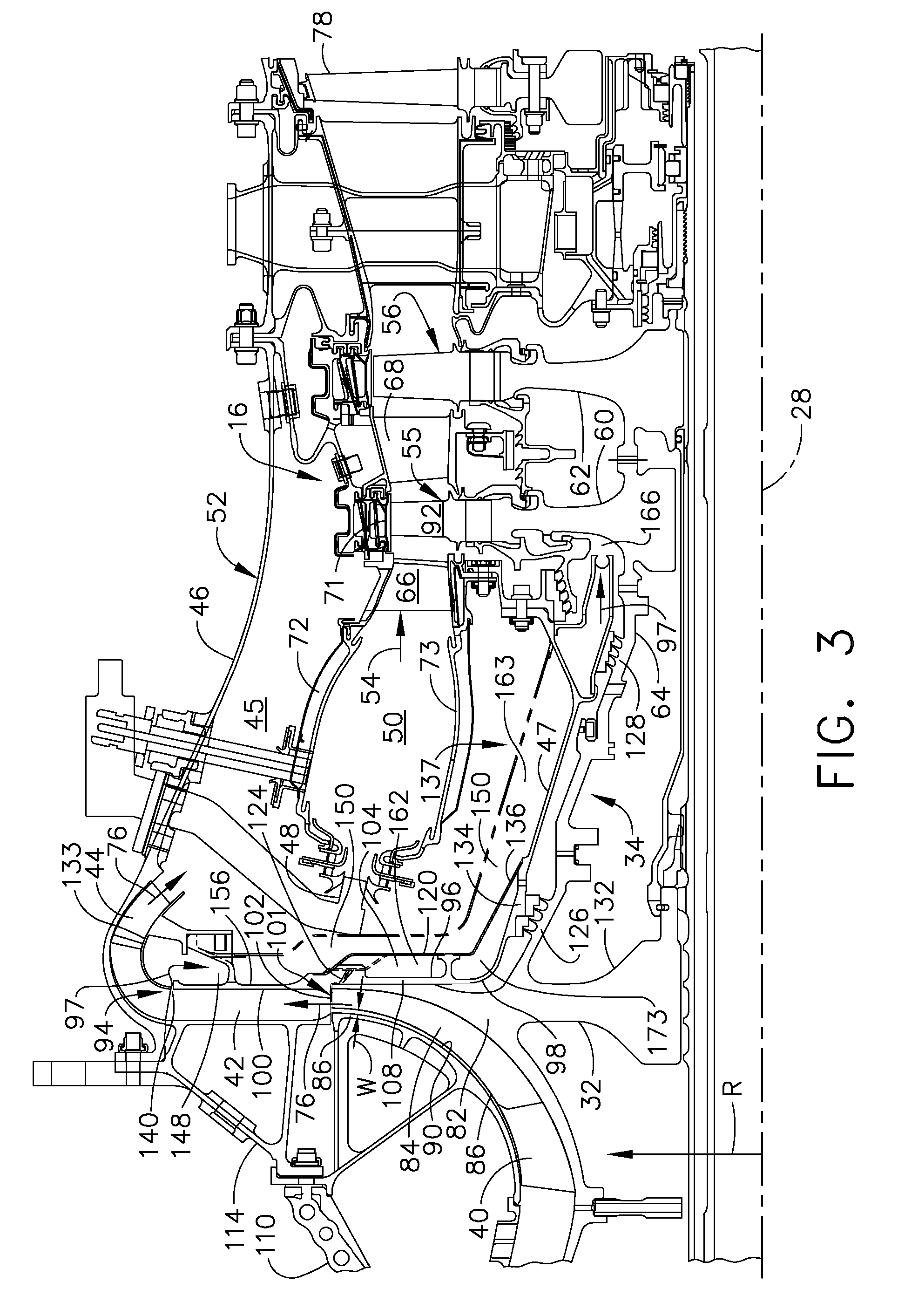
[0019]Illustrated in FIG. 1, gas turbine engine 8 with a high pressure gas generator 10 having a single stage centrifugal compressor 18 as a final compressor stage and an axial forward thrust apparatus 34 for maintaining a forward thrust on the high pressure rotor (12) for helping to maintain or control clearances or gaps between the high pressure rotor 12 and stator throughout the high pressure gas generator 10. Further referring to FIG. 2, the high pressure gas generator 10 has a high pressure rotor 12 including, in downstream flow relationship, a high pressure compressor 14, a combustor 52, and a high pressure turbine 16. The rotor 12 is rotatably supported about an engine centerline 28 by a forward bearing 20 in a front frame 22 and a rear bearing 24 disposed downstream of high pressure turbine 16 in a turbine frame 26.

[0020]The exemplary embodiment of the compressor 14 illustrated herein includes a five stage axial compressor 30 followed by the single stage centrifugal compress...


PUM


Abstract

A gas turbine engine turbine cooling system includes an impeller and a diffuser directly downstream of the impeller, a bleed for bleeding clean cooling air from downstream of the diffuser, and one or more channels in fluid communication with the bleed. Each of the channels having a generally radially extending section followed by a generally axially aftwardly extending section terminating at an annular cooling air plenum connected to accelerators. The radially and axially aftwardly extending sections may be connected by a bend section of the cooling air channel and the axially aftwardly extending section may be angled radially inwardly going from the bend section to the cooling air plenum. Each of the cooling channels includes an inner wall formed by a forward end wall extending radially outwardly from an inner combustor casing, an annular cover covering a radially inner portion of the forward end wall, and the inner combustor casing.

Description

GOVERNMENT INTERESTS[0001]This invention was made with government support under government contract No. N00019-06-C-0081 awarded by the Department of Defense. The government has certain rights to this invention.BACKGROUND OF THE INVENTION[0002]1. Technical Field[0003]The present invention relates generally to gas turbine engines having centrifugal compressors and, more specifically, supplying turbine cooling air from a centrifugal compressor.[0004]2. Background Information[0005]A conventional gas turbine engine typically includes a compressor, combustor and turbine, both rotating turbine components such as blades, disks and retainers, and stationary turbine components such as vanes, shrouds and frames routinely require cooling due to heating thereof by hot combustion gases. Cooling of the turbine, especially the rotating components, is important to the proper function and safe operation of the engine. Failure to adequately cool a turbine disk and its blading, for example, by providi...

Claims


Application Information

Patent Timeline
Patent Type & Authority Patents(United States)
IPC IPC(8): F02C1/00
CPCF02C3/08F02C6/08F02C7/18F01D9/045F04D29/4206F05D2250/324F05D2250/52F05D2260/15
Inventor OTTAVIANO, MARCUS JOSEPHPARKS, ROBERT JOHNNOON, JOHN LAWRENCED'ANDREA, MARK MICHAELREGAN, THOMAS MICHAEL
Owner GENERAL ELECTRIC CO
Why Eureka
Try Eureka