Method for press punching a hole in sheet metal and press die

a technology of press working and press die, which is applied in the direction of metal working equipment, etc., can solve the problems of piercing punch and piercing die defects, workpiece burrs, and piercing punch edges that cannot be pierced, so as to improve durability, reduce die fabrication cost, and ensure quality. the effect of punching

Inactive Publication Date: 2012-01-03
WANTS CO LTD +1
View PDF38 Cites 43 Cited by
  • Summary
  • Abstract
  • Description
  • Claims
  • Application Information

AI Technical Summary

Benefits of technology

[0017]The present invention has been devised in view of the above-described circumstances, and its object is to provide a punch unit which allows a certain degree of axial offset between the piercing punch and the piercing die, permits high-quality punching reliably without using a complex slide cam mechanism, improves durability over the conventional art, and thereby makes it possible to lower the die fabrication cost, shorten the period of die fabrication, and reduce the die repairing cost, as well as a press die and a punching method using this punch unit.
[0024]In accordance with the present invention, the planning of a complex die structure for ensuring the axial accuracy of the piercing punch and the piercing die and manual operations for enhancing the die fabrication accuracy become unnecessary. Thus it is possible to reduce the number of die fabrication steps and shorten periods of die design and fabrication.
[0025]In addition, in accordance with the present invention, it is unnecessary to use a complex and expensive slide cam structure in a case where punching work is effected with respect to a plate surface of a workpiece which is inclined with respect to the pressing direction. Since the fabrication cost associated with the slide cam and the operation of aligning the piercing punch and the piercing die are not required, it is possible to reduce the die fabrication cost and shorten the period of die fabrication.
[0026]Furthermore, in accordance with the present invention, since the slide cam structure which is mounted on the upper die holder or the lower die is unnecessary, it is possible to simultaneously effect punching in a plurality of different plate surfaces of the workpiece, and the peripheral edge cutting work and punching work can be effected simultaneously. Therefore, the number of press working steps can be reduced substantially, and the number of dies can be decreased, so that it is possible to lower the die cost and shorten the periods of die design and fabrication.
[0027]In addition, in accordance with the present invention, it is possible to reduce the repairing cost for correcting axial offset between the piercing punch and the piercing die occurring due to the wear of slide surfaces of upper and lower dies and cam slide surfaces at the time of mass production.

Problems solved by technology

If this clearance cannot be maintained, burrs can occur in the workpiece, or defects of punching edges of the piercing punch and the piercing die or the breakage of the piercing punch can occur owing to the interference between the piercing punch and the piercing die.
In addition, in a case where a hole is punched in a plate surface which is inclined with respect to the press working direction, since the piercing punch tends to escape in the direction of inclination to make it impossible to maintain the clearance, and since the breakage of the punch occurs, a slide cam mechanism is conventionally provided, and the punch is held by this slide cam mechanism to force out the punch in a direction different from the pressing direction.
For this reason, this structure is not used since it is difficult to maintain the clearance between the piercing punch and the die necessary for the conventional punching method.
However, with this other slide cam mechanism, since not only is this cam mechanism itself expensive, but a multiplicity of dies are required for manufacturing a single pressed part, since it is impossible to effect the simultaneous cutting work of outer peripheral edges of a pressed part and the simultaneous piercing work of a plurality of different surfaces.
In addition, in the process of manufacturing pressed parts, there is a problem in that large repairing cost is involved for maintaining the axial accuracy of the piercing punch and the piercing die.
Therefore, even if further pressurization is effected, it is impossible to transmit tension for punching a hole in the workpiece, with the result that it is impossible to fracture over the entire region of the outer periphery of the hole portion of the piercing die, making it impossible to obtain a satisfactory hole configuration.
In addition, there is another problem in that the pressure medium typified by urethane rubber is shaved off by the sharp edge portion of the piercing die hole, so that the pressure medium lacks durability.

Method used


Image

  • Method for press punching a hole in sheet metal and press die
  • Method for press punching a hole in sheet metal and press die
  • Method for press punching a hole in sheet metal and press die

Examples


Embodiment Construction

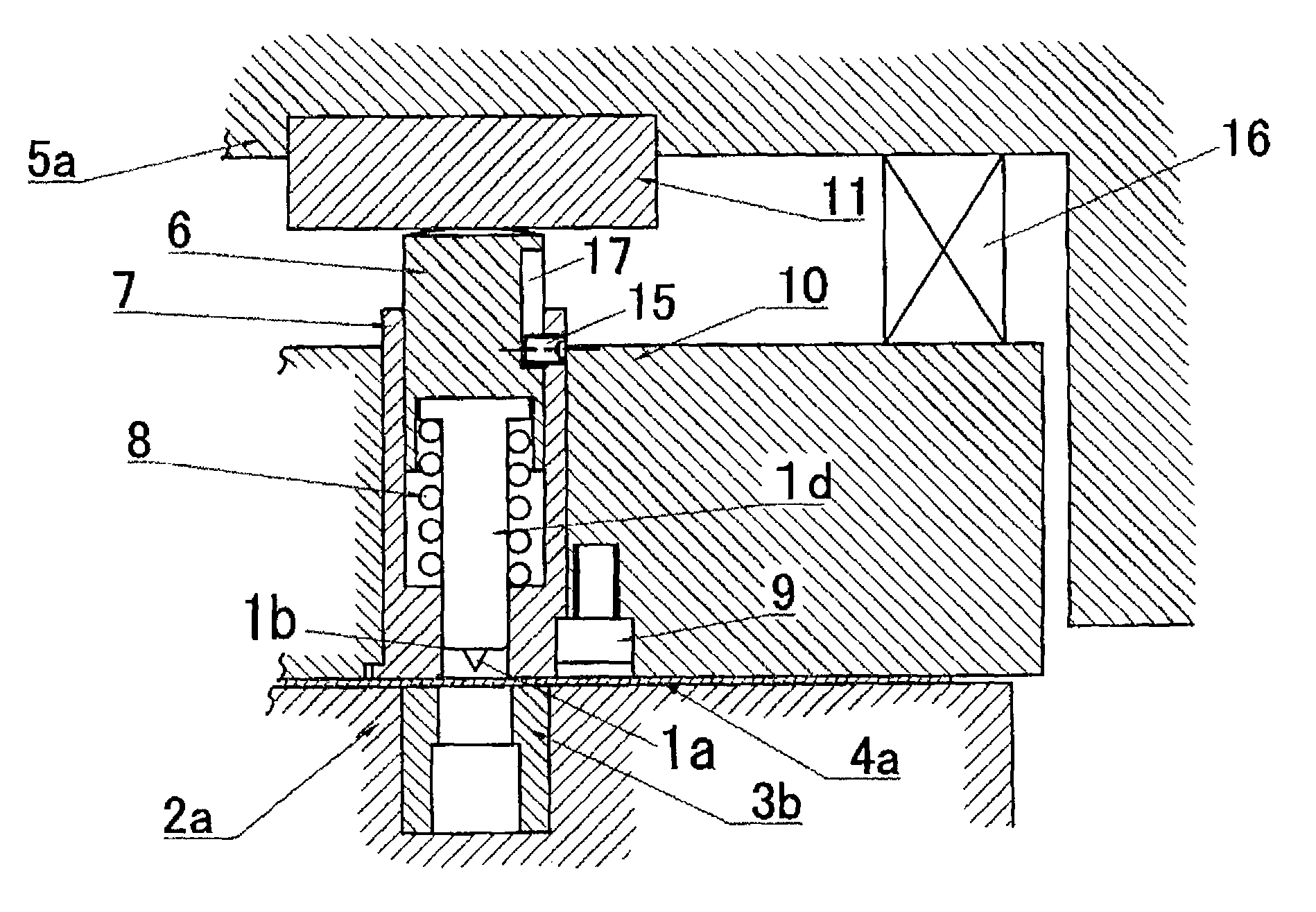
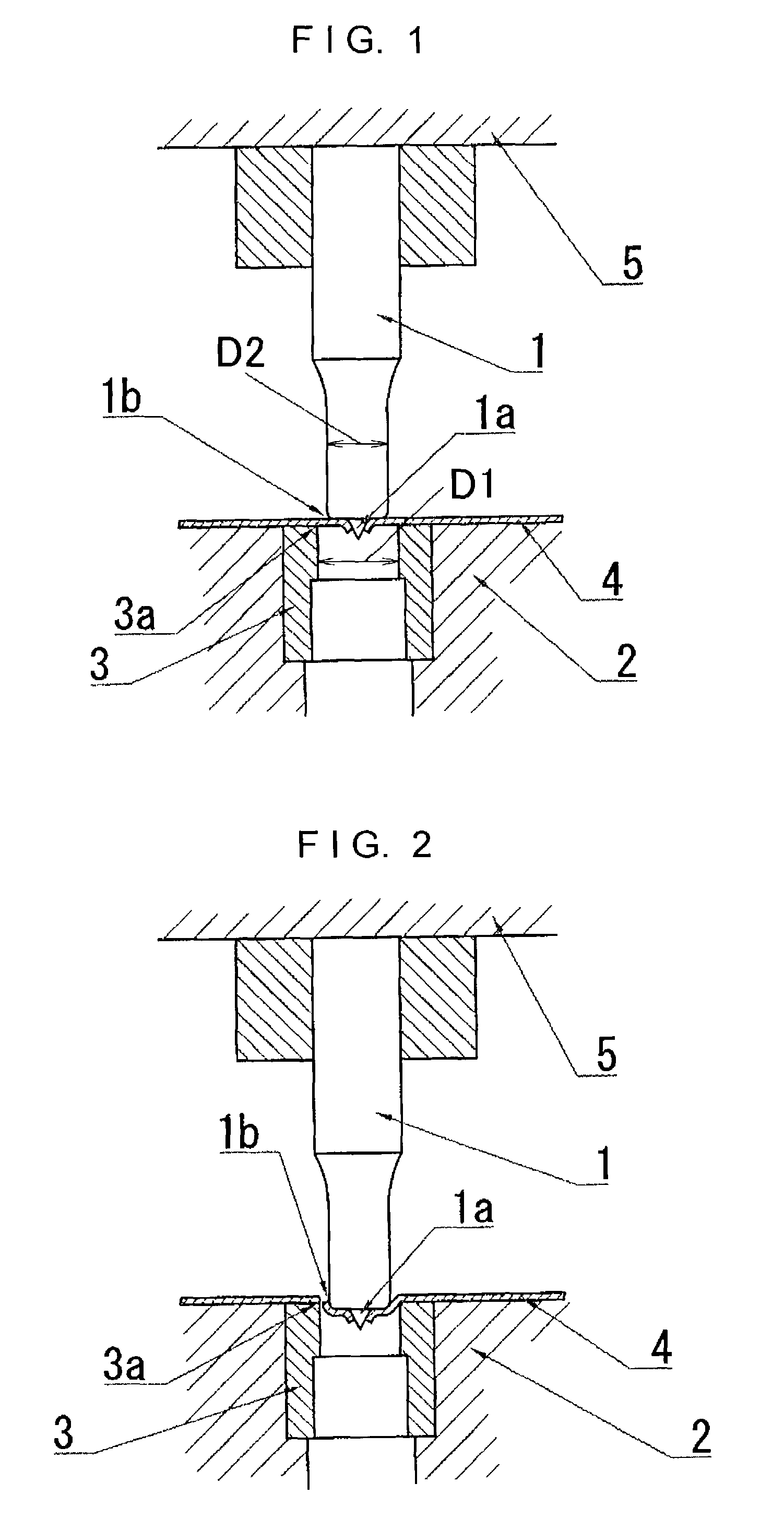
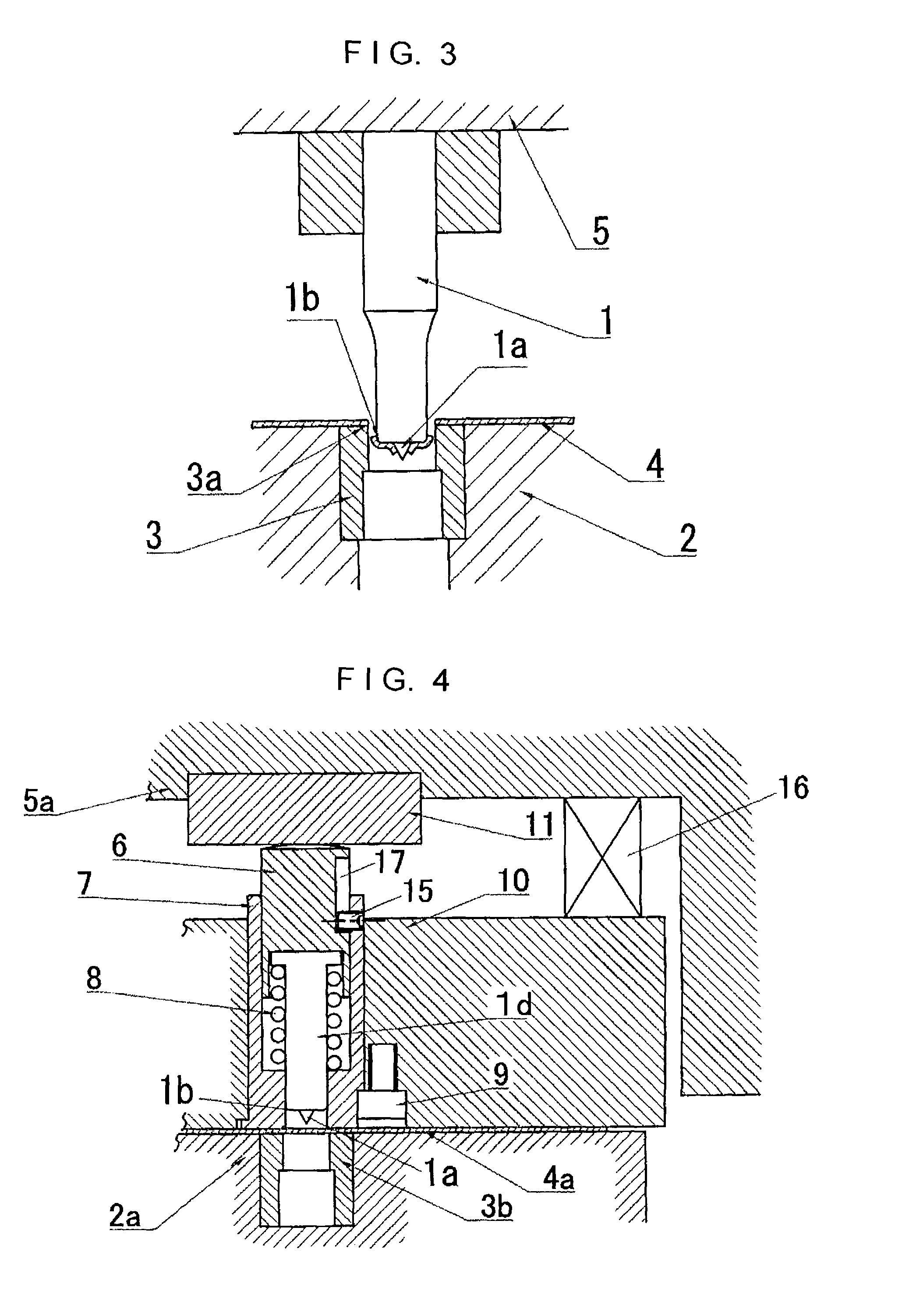
[0035]In FIGS. 1 to 3, a press die for punching is comprised of a piercing die 3 buried in a lower die 2 as well as a piercing punch 1 held by an upper die 5. The piercing punch 1 has a smaller diameter D2 than in a case where it is used in shearing work with respect to a diameter D1 of the hole of the piercing die 3, and the piercing punch 1 has at its tip a sharp projection 1a for piercing a workpiece 4. In such a piercing punch 1, an outer peripheral edge portion 1b of the tip where the sharp projection 1a is provided is rounded.

[0036]In a case where punching is effected by the press die for punching shown in FIGS. 1 to 3, the workpiece 4 formed of sheet metal is placed on the lower die 2 including the piercing die 3, and as the upper die 5 is lowered, the piercing punch 1 is pressed against the workpiece 4. Thus, as shown in FIG. 1, in the initial period of working, the sharp projection 1a provided on the piercing punch 1 is first brought into contact with the workpiece 4, there...


PUM

PropertyMeasurementUnit
diameteraaaaaaaaaa
pressureaaaaaaaaaa
tensionaaaaaaaaaa

Abstract

A punch unit for a press die is provided for punching a hole in sheet metal. The punch unit includes a piercing punch provided with a sharp projection, a plunger for pressing the piercing punch, a cylinder for supporting the piercing punch and the plunger slidably in a punching direction, and a coil spring for retracting the piercing punch and the plunger. Also disclosed is a press die for punching a hole in sheet metal using the punch unit.

Description

BACKGROUND OF THE INVENTION[0001]1. Field of the Invention[0002]The present invention relates to a method for punching a hole in a sheet metal by press working and a press die.[0003]2. Description of the Related Art[0004]Conventionally, in a case where a hole is punched in a sheet metal by press working, it is the general practice to place a workpiece on a piercing die having a punching hole and subsequently to lower an upper die having a piercing punch so as to effect shearing work with respect to the workpiece by the punch and the die.[0005]In the case where work is effected using such a conventional technique, it is normally necessary to control the clearance between the piercing punch and the piercing die to within plus 0.01 millimeter and minus 0.01 millimeter. If this clearance cannot be maintained, burrs can occur in the workpiece, or defects of punching edges of the piercing punch and the piercing die or the breakage of the piercing punch can occur owing to the interference ...

Claims


Application Information

Patent Timeline
Patent Type & Authority Patents(United States)
IPC IPC(8): B26F1/14B21D28/26
CPCB21D28/26Y10T83/04Y10T83/0586Y10T83/2155Y10T83/2159Y10T83/217Y10T83/8727Y10T83/9423Y10T83/9428
Inventor OISHI, MASATOSHI
Owner WANTS CO LTD
Why Eureka
Try Eureka