Planar magnetic structure

a magnetic structure and planar technology, applied in the direction of instruments, inductances, reradiation, etc., can solve the problems of increasing transformer capacitance and eddy current losses, excessive copper losses of conventional structures, and increasing transformer capacitance and winding losses, so as to reduce the voltage gradient and reduce the voltage gradient

Active Publication Date: 2012-01-03
RAYTHEON CO
View PDF35 Cites 59 Cited by
  • Summary
  • Abstract
  • Description
  • Claims
  • Application Information

AI Technical Summary

Benefits of technology

[0006]This invention features a planar magnetic structure including a printed wiring board having at least one winding segment, an inner clearance through the printed wiring board within the winding segment, and at least one outer clearance through the printed wiring board external to the winding segment. There is a core having an inner leg extending through the inner clearance and at least one outer leg extending through the outer clearance defining a gap occupied by the winding segment. An inner shield is disposed between the inner clearance and the inner core leg. The inner shield surrounds the inner leg but is less than one turn defining a shield gap. The shields reduce the voltage gradient between the core legs and the winding segment. There is at least one outer electrostatic shield between the outer clearance and the at least one core outer leg, the outer shield is disposed between the outer leg and inner leg and a guard barrier proximate the shield gap and between the shield gap and the winding segments reduces the voltage gradient between the inner shield end at the gap and the winding segment.

Problems solved by technology

However, conventional structures suffer from excessive copper losses and rely on the increased spacing between windings and the core to prevent corona inception and insulation breakdown.
This conventional approach has several problems.
The fact that voltage breakdown of air is sensitive to changes in humidity and altitude farther complicates this problem.
Added capacitance and increased winding losses can be caused by electrostatic shields.
However, they increase transformer capacitance and eddy current losses.

Method used


Image

  • Planar magnetic structure
  • Planar magnetic structure
  • Planar magnetic structure

Examples


Embodiment Construction

[0025]Aside from the preferred embodiment or embodiments disclosed below, this invention is capable of other embodiments and of being practiced or being carried out in various ways. Thus, it is to be understood that the invention is not limited in its application to the details of construction and the arrangements of components set forth in the following description or illustrated in the drawings. If only one embodiment is described herein, the claims hereof are not to be limited to that embodiment. Moreover, the claims hereof are not to be read restrictively unless there is clear and convincing evidence manifesting a certain exclusion, restriction, or disclaimer.

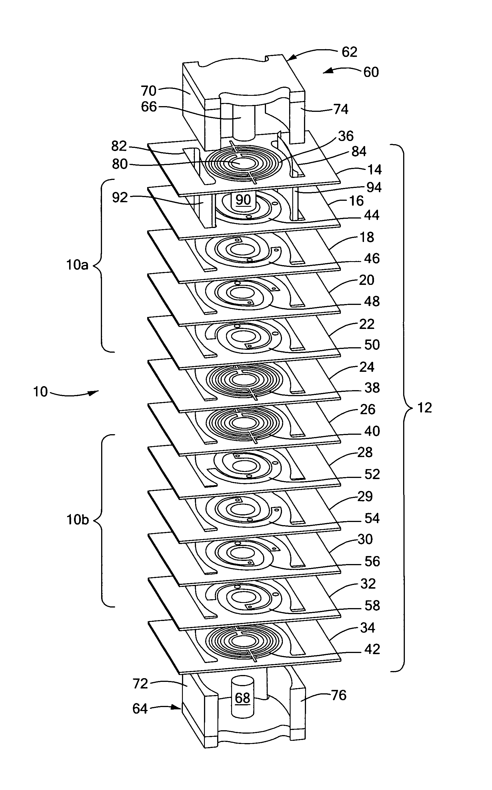
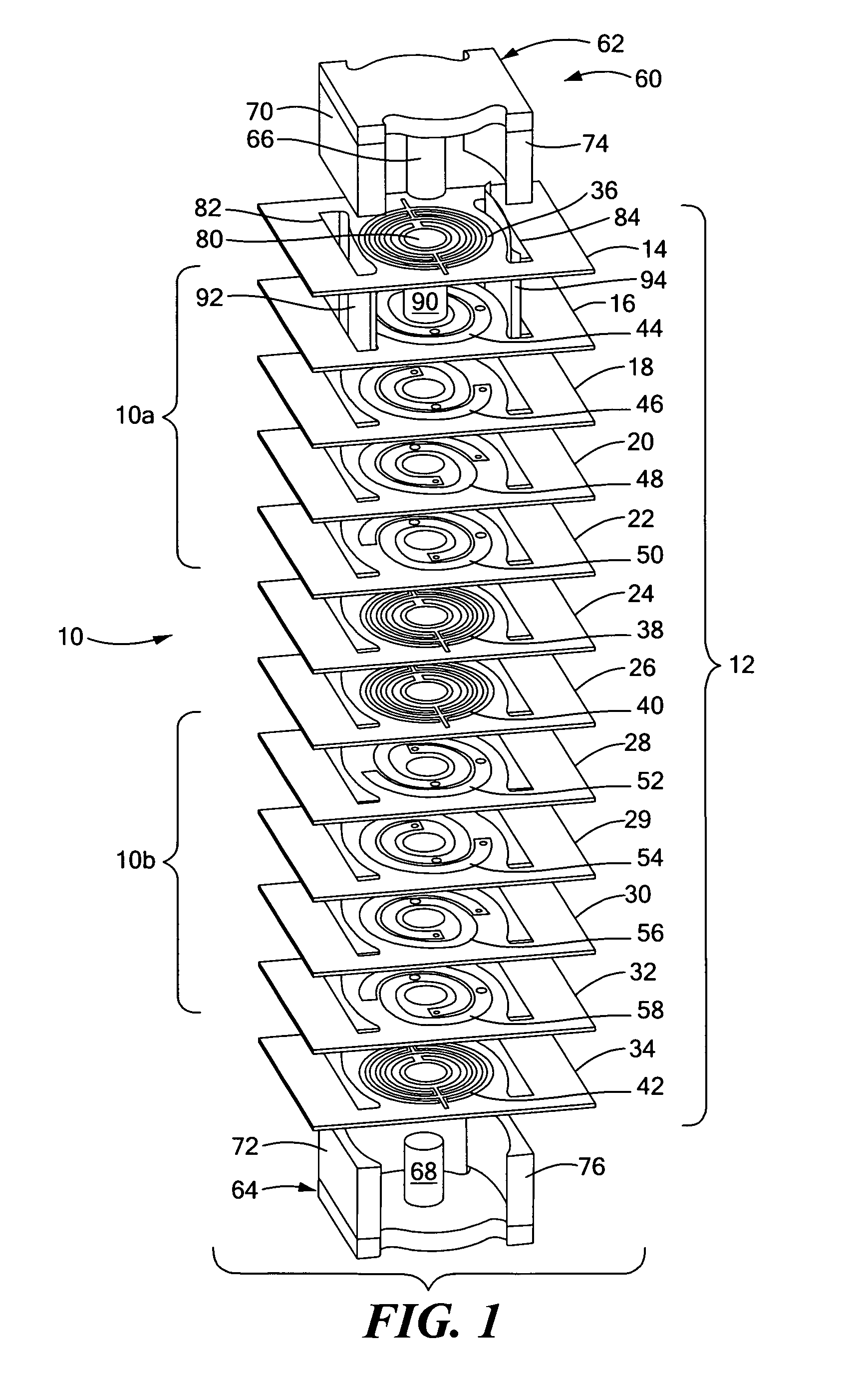
[0026]There is shown in FIG. 1 an embodiment of this invention in a transformer 10 having a primary winding 10a and secondary winding 10b constructed on a multi-layer circuit board 12 formed of a stacked array of twelve layers 14, 16, 18, 20, 22, 24, 26, 28, 30, 32, 34. Layers 14-24 are associated with primary winding 10a w...


PUM

PropertyMeasurementUnit
magnetic structureaaaaaaaaaa
voltageaaaaaaaaaa
planar magnetic structureaaaaaaaaaa

Abstract

An improved planar magnetic structure in which the voltage gradient between core and windings is reduced by shields disposed between the one or more legs of the core and the windings and extending through the PWB layers; vias are offset to permit them to be contained within the path of the winding; and the induced magnetic and eddy currents intrinsic to interstitial shield layers are reduced by configuring the shield conductors with pairs of courses with opposite and offsetting current propagation.

Description

FIELD OF THE INVENTION[0001]This invention relates to an improved planar structure with reduced voltage gradient between windings and core, compact placement of vias within the winding path, and improved shields to reduce induced magnetic fields.BACKGROUND OF THE INVENTION[0002]Using planar magnetics allows the reduction in height of magnetic components and increase in power density for state-of-the-art DC / DC converters. However, conventional structures suffer from excessive copper losses and rely on the increased spacing between windings and the core to prevent corona inception and insulation breakdown. This conventional approach has several problems.[0003]Corona discharge and eventual insulation breakdown can be caused by voltage concentration across the air gap between the magnetic core and the printed wiring board (PWB). Insulation that supports AC voltages includes air (the gap between the core and the edge of the board) and solid material inside the PWB. When voltage is applie...

Claims


Application Information

Patent Timeline
Patent Type & Authority Patents(United States)
IPC IPC(8): H01F27/36H01F5/00H01F17/04H01F27/28
CPCH01F27/2804H01F27/2885H01F2027/2809H01F2027/2819
Inventor JACOBSON, BORIS S.BARNETT, MARK P.
Owner RAYTHEON CO
Why Eureka
Try Eureka