Flicker correction apparatus, flicker correction method, and image sensing apparatus

a flicker correction and flicker correction technology, applied in the field of flicker correction apparatus and flicker correction method, can solve the problems of flicker correction accuracy degrade, flicker detection accuracy and flicker correction accuracy decrease, etc., and achieve the effect of accurate correction

Inactive Publication Date: 2012-01-03
CANON KK
View PDF5 Cites 64 Cited by
  • Summary
  • Abstract
  • Description
  • Claims
  • Application Information

AI Technical Summary

Benefits of technology

[0009]The present invention has been made in consideration of the above-described problems of the prior arts. It is an object of the present invention to provide a flicker correction apparatus and flicker correction method which accurately corrects, using a simple arrangement, a flicker component contained in an image sensed under a light source whose brightness periodically changes.

Problems solved by technology

However, since the shutter speed is fixed in this method, the degree of freedom of exposure control decreases.
In the flicker detection method described in Japanese Patent No. 3823314, if the object or camera moves, it is difficult to discriminate between the motion component and the flicker component in the sensed image, resulting in a decrease in the flicker detection accuracy and the flicker correction accuracy.
Additionally, the sensed image may contain color information inappropriate for flicker detection.
The flicker correction accuracy degrades in such an image.

Method used


Image

  • Flicker correction apparatus, flicker correction method, and image sensing apparatus
  • Flicker correction apparatus, flicker correction method, and image sensing apparatus
  • Flicker correction apparatus, flicker correction method, and image sensing apparatus

Examples


first embodiment

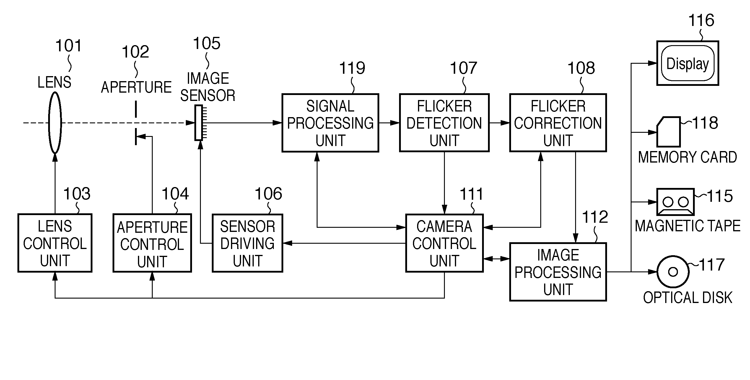
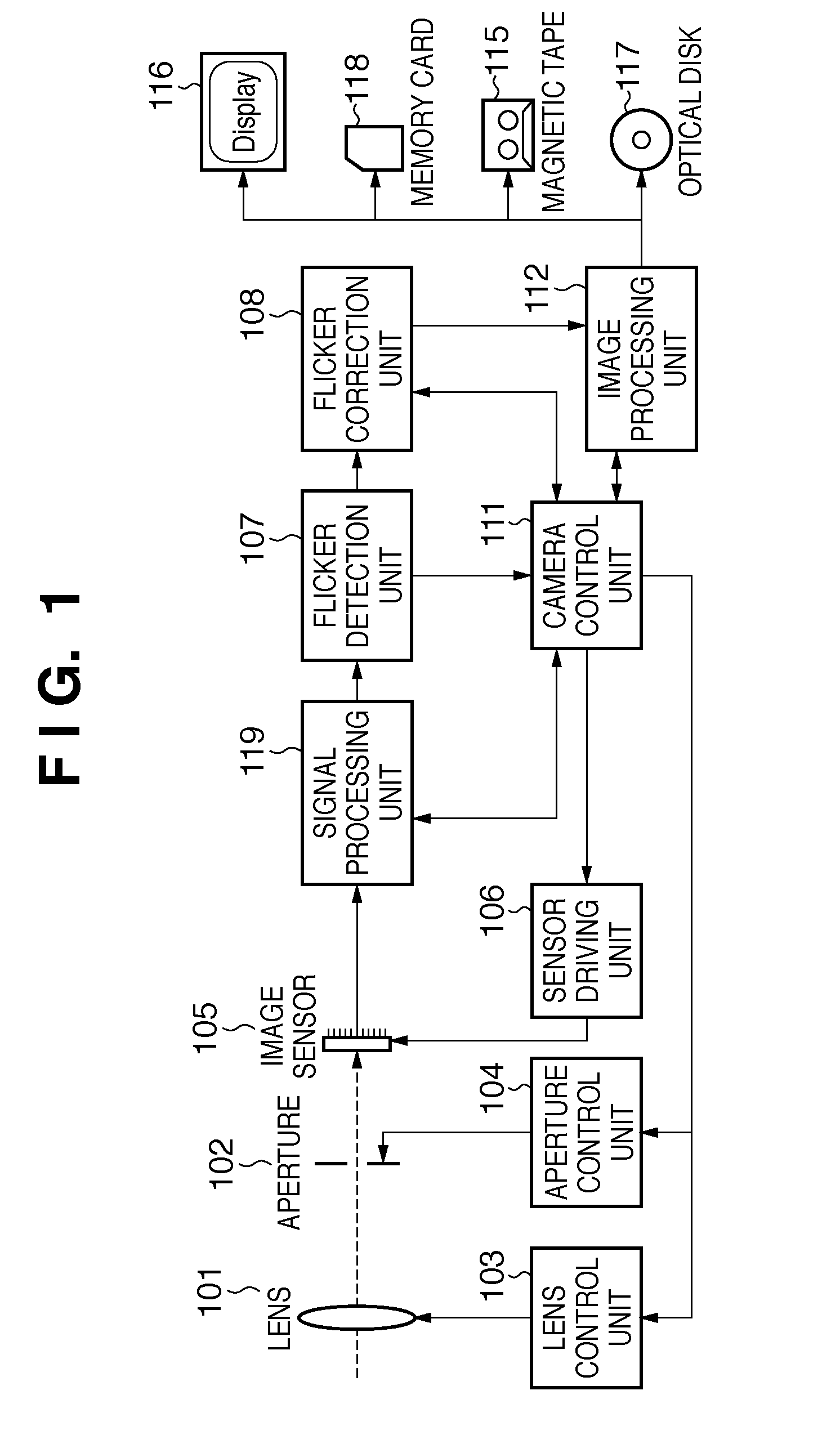
[0022]FIG. 1 is a block diagram showing an example of the arrangement of an image sensing apparatus which is an example of a flicker correction apparatus according to the first embodiment of the present invention.

[0023]Reference numeral 101 denotes a lens. An aperture 102 is arranged on the rear side of the lens 101. Light which enters via the lens 101 and the aperture 102 forms an object image on the imaging plane of an image sensor 105. The image sensor 105 is, for example, a CMOS image sensor of X-Y addressing type, which converts the formed object image into an image signal of each pixel.

[0024]A signal processing unit 119 performs signal processing such as defect pixel correction, A / D conversion, and color interpolation processing for the image signal converted by the image sensor 105, thereby generating image data (CCD-RAW data: to be simply referred to as RAW data hereinafter).

[0025]A flicker detection unit 107 detects whether the RAW data output from the signal processing uni...

second embodiment

[0063]The second embodiment of the present invention will be described next. The second embodiment is the same as the first embodiment except flicker detection and correction processing by a flicker detection unit 107 and a flicker correction unit 108.

[0064]The flicker detection and correction processing executed by the flicker detection unit 107 and the flicker correction unit 108 of the image sensing apparatus according to this embodiment will be described below with reference to the flowchart in FIG. 6.

[0065]The same step numbers as in FIG. 3 of the first embodiment denote the same operations in FIG. 6, and a description thereof will not be repeated.

[0066]As is apparent from comparison between FIGS. 6 and 3, the second embodiment is different in flicker detection region selection processing for each vertical position.

[0067]In step S105, the flicker detection unit 107 extracts flicker detection regions in which the average luminance value and the average color difference values fa...

third embodiment

[0079]The third embodiment of the present invention will be described next. The third embodiment is the same as the first embodiment except flicker detection and correction processing by a flicker detection unit 107 and a flicker correction unit 108.

[0080]The flicker detection and correction processing executed by the flicker detection unit 107 and the flicker correction unit 108 of the image sensing apparatus according to this embodiment will be described below with reference to the flowchart in FIG. 7.

[0081]The same step numbers as in FIG. 3 of the first embodiment denote the same operations in FIG. 7, and a description thereof will not be repeated.

[0082]In step S303, the flicker detection unit 107 allocates flicker detection regions to RAW data of one frame output from a signal processing unit 119, as in the first embodiment. As the luminance value of each flicker detection region, the flicker detection unit computes the average luminance value of not all pixels in the region but...


PUM


Abstract

A flicker detection region in which an image signal has values relating to luminance and colors within predetermined ranges is extracted from a plurality of flicker detection regions allocated in the vertical and horizontal directions of an image. A flicker component is detected using the luminance information of the image signal in the extracted flicker detection region. A correction value to correct the flicker component is generated from the detected flicker component. This makes it possible to accurately correct, using a simple arrangement, a flicker component contained in an image sensed under a light source whose brightness periodically changes even when the object or the image sensing apparatus moves.

Description

BACKGROUND OF THE INVENTION[0001]1. Field of the Invention[0002]The present invention relates to a flicker correction apparatus and flicker correction method, and more particularly, to a flicker correction apparatus and flicker correction method which correct a flicker component contained in an image sensed under a light source whose brightness periodically changes.[0003]2. Description of the Related Art[0004]Conventionally, an image sensing apparatus using a solid-state image sensor of X-Y addressing type, such as a CMOS image sensor, is commercially available. When shooting is performed using such an image sensing apparatus under the illumination of, for example, a fluorescent lamp or tungsten-filament lamp whose brightness varies in synchronization with the power supply frequency, the sensed image may have periodical bright and dark patterns in the vertical direction. This phenomenon, which is called flicker, occurs due to the difference between the commercial power supply freque...

Claims


Application Information

Patent Timeline
Patent Type & Authority Patents(United States)
IPC IPC(8): H04N5/228H04N5/21H04N5/235
CPCH04N5/235H04N5/2357H04N23/70H04N23/745
Inventor URISAKA, SHINYA
Owner CANON KK
Why Eureka
Try Eureka