
Humidity control for air conditioning system

a technology of humidity control and air conditioning system, which is applied in the direction of domestic cooling equipment, heating types, instruments, etc., can solve the problems of controlling the airflow of the indoor air circulating fan or blower, and achieve the effect of avoiding an increase in humidity

Active Publication Date: 2012-01-10
TRANE INT INC
View PDF43 Cites 168 Cited by
  • Summary
  • Abstract
  • Description
  • Claims
  • Application Information

AI Technical Summary

Benefits of technology

[0003]The present invention provides an improved method for controlling humidity in an enclosed space being served by an air conditioning system. The invention also comprises an improved system for controlling the humidity being sensed in an enclosed space to avoid an increase in humidity as a consequence of continued operation of an indoor air circulating fan or blower.

Problems solved by technology

However, a common problem in the art of forced air flow air conditioning or so-called cooling equipment, in particular, is control of the indoor air circulating fan or blower to avoid evaporation of condensate collecting on the cooling coil or heat exchanger and in any condensate collecting pans which may be interposed in the air flow stream.

Method used


Image

  • Humidity control for air conditioning system
  • Humidity control for air conditioning system
  • Humidity control for air conditioning system

Examples


Embodiment Construction

[0012]In the description which follows like elements are marked throughout the specification and drawing with the same reference numerals, respectively. The drawing figures are not necessarily to scale and certain features may be shown exaggerated in scale or in somewhat schematic or generalized form in the interest of clarity and conciseness.

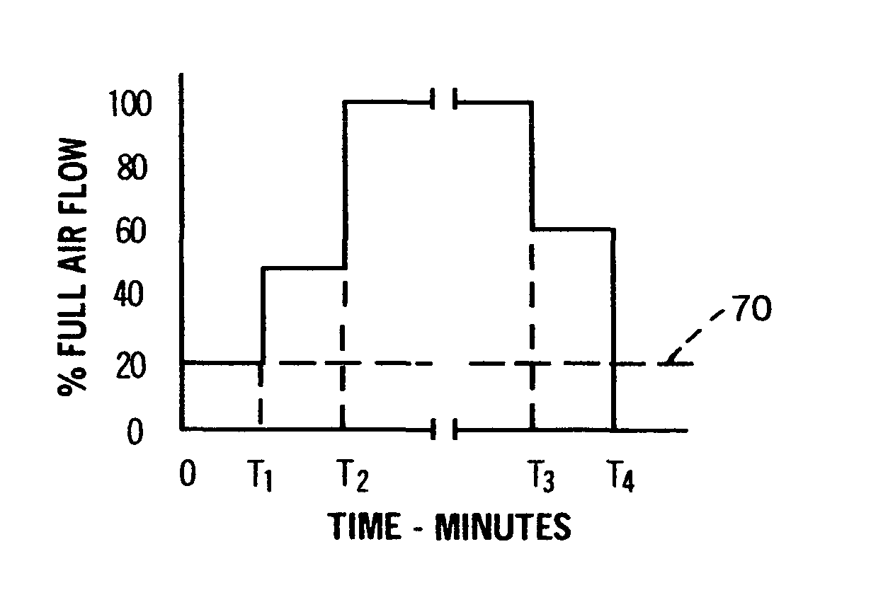
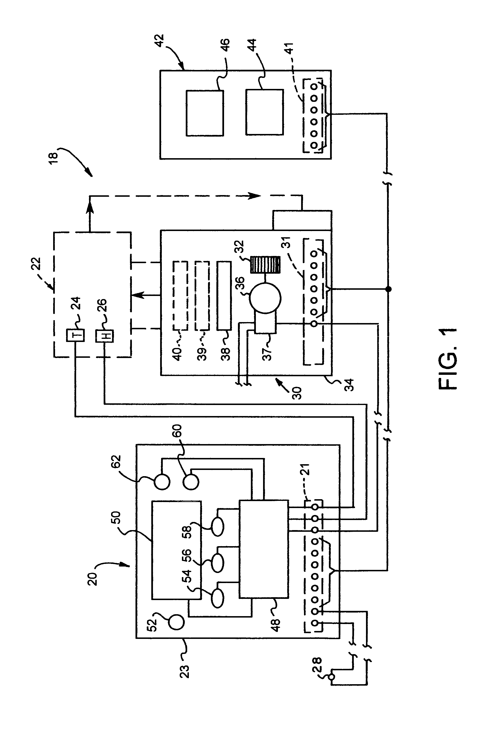
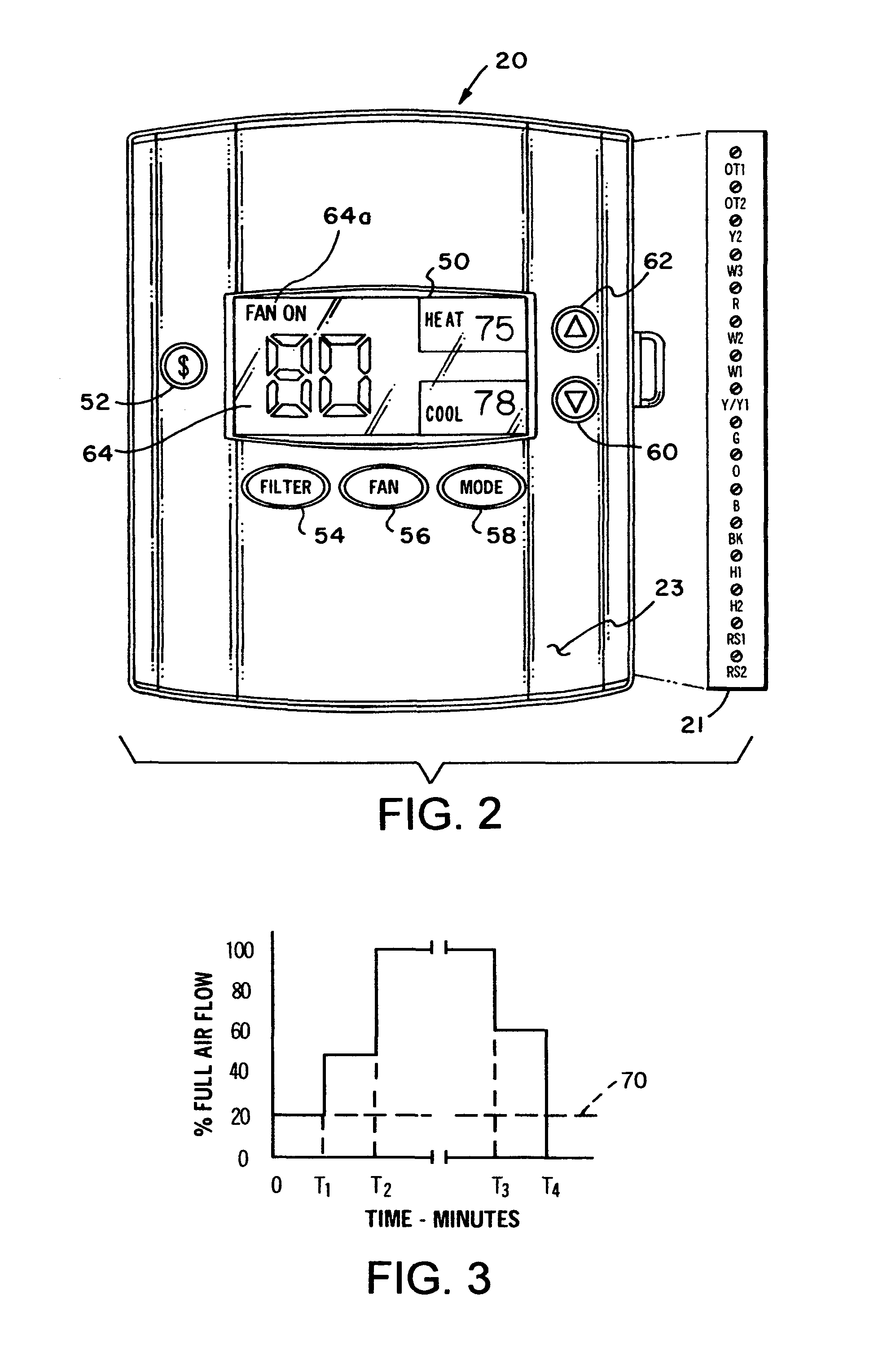
[0013]Referring to FIG. 1, there is illustrated a schematic diagram an HVAC system 18 which includes a thermostat generally designated by the numeral 20. The thermostat 20 includes certain sensors for sensing the temperature of an enclosed space 22 including a temperature sensor 24 and also a humidity sensor 26 for sensing the relative humidity in the space 22. The thermostat controller 20 may also include a temperature sensor 28 for sensing the so-called outdoor temperature surrounding the enclosed space 22. Enclosed space 22 may be a private residential dwelling or one or more rooms or spaces in a commercial building, for example. The tempera...


PUM


Abstract

In an air conditioning system for circulating cooled air to an enclosed space, a controller including a temperature sensor, a humidity sensor and a microcontroller for controlling the indoor fan or blower to prevent operation of same if a fan run-on mode is selected or continuous fan operation is selected and the humidity sensed in the enclosed space is greater than a predetermined amount. Continuous fan operation is allowed unless the humidity exceeds a user defined setpoint during an air cooling operating mode. If the humidity sensed is greater than the predetermined amount, the fan is operated only when the system is providing cooled air, such as when the system compressor is energized.

Description

BACKGROUND OF THE INVENTION[0001]In the art of heating, ventilating and air conditioning (HVAC) equipment, there has been a continuing need and desire to provide a system and method for controlling air flow to and from an enclosed space wherein the humidity level is controlled to the desires of the occupants of the space. In this regard controls have been developed which include a humidity sensor and an associated controller providing for adding moisture to the air flow stream or reducing the humidity level by over cooling and reheating the air, for example, and by operation of humidity providing or dehumidification processes and equipment.[0002]However, a common problem in the art of forced air flow air conditioning or so-called cooling equipment, in particular, is control of the indoor air circulating fan or blower to avoid evaporation of condensate collecting on the cooling coil or heat exchanger and in any condensate collecting pans which may be interposed in the air flow stream...

Claims


Application Information

Patent Timeline
Patent Type & Authority Patents(United States)
IPC IPC(8): F25D17/06F25B49/00F25D17/04
CPCF24F11/0008G05D22/02F24F2011/0064F24F11/0015F24F11/30F24F2110/20F24F11/65F24F11/74
Inventor CRAWFORD, ROY R.
Owner TRANE INT INC
Learn More