
Illuminated directional wind speed indicator

a technology of wind speed indicator and directional wind speed, which is applied in the direction of measurement devices, instruments, sports apparatus, etc., can solve the problems of aviators having a difficult time gauging wind speed at night, complicated devices, and the propeller at the front of the aerovane which provides relative wind speed information is not illuminated, so as to achieve high lumen output, reduce power consumption, and high efficiency

Active Publication Date: 2012-01-10
SAUDI ARABIAN OIL CO
View PDF22 Cites 6 Cited by
  • Summary
  • Abstract
  • Description
  • Claims
  • Application Information

AI Technical Summary

Benefits of technology

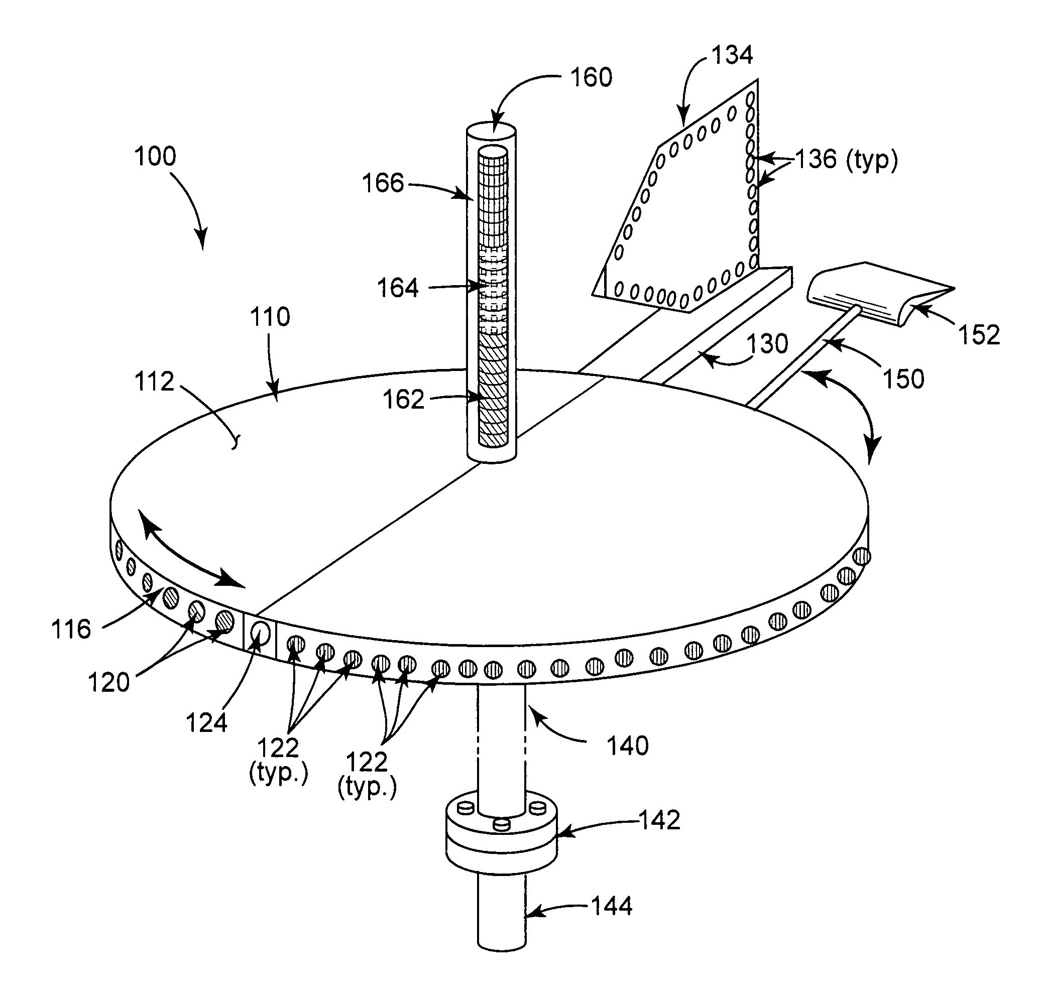
The present invention is an improved wind direction and wind speed indicator that provides greater visibility of both indications at night and under other conditions of poor visibility. The wind direction indicator includes a mast-mounted rotatable central body member, a rudder or windvane attached to the body member, and lights mounted on the edge of the central body and on the sides of the rudder. The anemometer portion of the invention takes the form of a wind activated airfoil or paddle and lever assembly linked electromechanically to an associated vertically arrayed light display to indicate wind speed. The LEDs of the preferred embodiment allow the device to be seen at a greater distance than a pilot can view a traditional windsock. The apparatus and its components can be constructed of a scale and positioned at a location relative to the landing zone to accommodate the specific type of aircraft that typically utilize the runway. The invention can also be utilized to provide a highly visible wind direction indicator to workers evacuating an industrial chemical production facility during an emergency such as a release of hazardous gas, when it would be important to know the prevailing wind direction in order to select the safest evacuation route.

Problems solved by technology

However, the propeller at the front of the aerovane which provides relative wind speed information is not illuminated.
Aviators would therefore have a difficult time gauging wind speed at night.
The spring and gear mechanism complicate this device, and the distance at which the dial may be read is not great.
In addition, the apparatus is not illuminated for nighttime use.
The design is complicated because of the need to control the pivoting arms.
The devices of the prior art have limited ability for use in regions that may experience conditions of blowing sand and dust at ground level due to complex mechanical systems that could become fouled and that would require frequent inspection and maintenance to assure their continued reliable operation.
Apparatus that display numbers also present problems of deciphering the numerals at a distance as the pilot is approaching the runway or landing strip.

Method used


Image

  • Illuminated directional wind speed indicator
  • Illuminated directional wind speed indicator
  • Illuminated directional wind speed indicator

Examples


Embodiment Construction

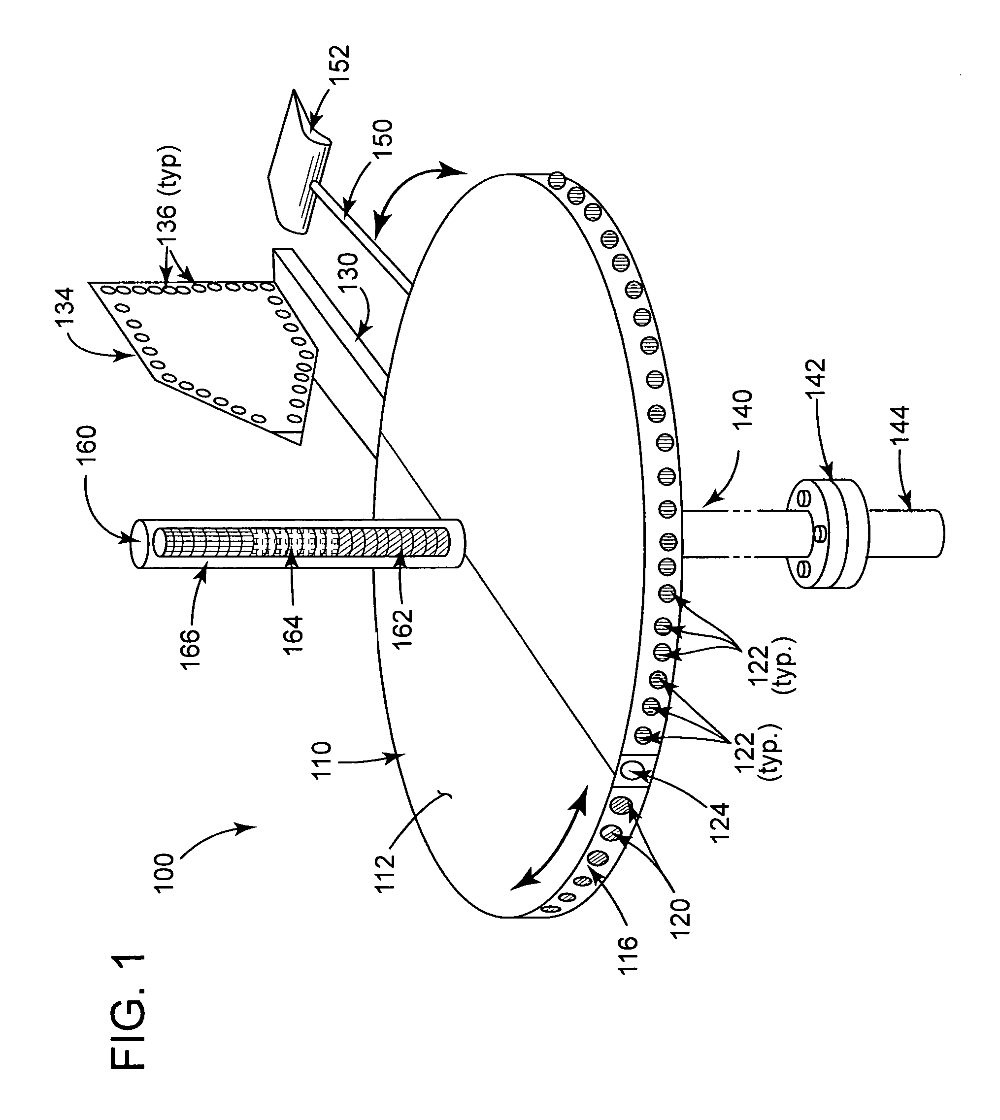
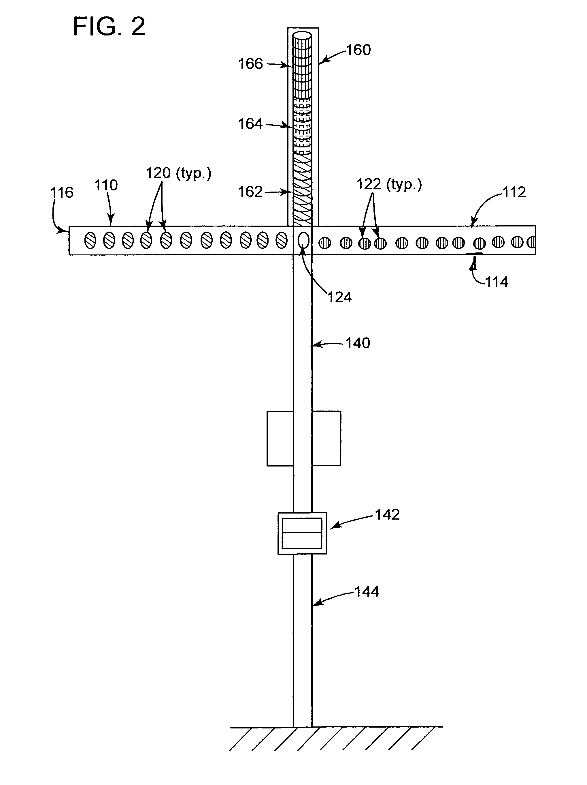
[0037]Referring to FIGS. 1 and 2, the illuminated directional wind speed indicator 100 includes a rotationally-mounted base member in the form of a rotatable enclosure 110 with top surface 112, bottom surface 114 (not shown) and side 116. In the embodiment shown in FIGS. 1 and 2, the rotatable enclosure 110 is shaped as a disk or short cylinder of generally circular cross-section. As will be apparent from this description, other non-circular configurations can be employed for the base member.

[0038]A plurality of high intensity light-emitting diodes (LEDs) of predetermined and readily distinguishable colors are mounted along the periphery or the side of the rotatable enclosure 110. For example, the right side can be fitted with an array of green LEDs 120 arranged with equal angular spacing and the left side provided with an array of red LEDs 122. The rotatable enclosure 110 has a forward central portion on which is mounted one or more white LEDs 124 and an aft or rear central portion...


PUM


Abstract

A combination wind direction and wind speed indicating apparatus for providing enhanced visibility at night and under other low visibility conditions is mounted, for example, at an airport landing zone, to rotate in the wind and indicates wind direction with high-intensity colored lights mounted in a specified array about the horizontal periphery of the apparatus; a vertical array of lights is illuminated in response to incremental wind speed variations. The apparatus can include a self-contained source of electrical power such as a rechargeable battery pack connected via appropriate circuitry to a solar power cell.

Description

BACKGROUND OF THE INVENTION[0001]1. Field of the Invention[0002]This invention relates to a wind direction and speed indicator, and in particular, to an improved apparatus design that provides greater visibility of the indicator at night and during other low visibility conditions.[0003]2. Description of the Related Art[0004]Airplane pilots who are approaching an airport or landing strip need to know the ground wind direction and relative speed in order to safely land their craft. A number of devices are in use, or have been proposed to assist aviators by indicating wind direction and speed.[0005]Since antiquity, wind vanes have been used for indicating wind direction and some airports continue to use wind vanes for this purpose. For example, the Whitehorse International Airport in Yukon Territory, Canada, has mounted a retired commercial aircraft, a Douglas DC-3, to serve as a wind vane for the airport. Relative wind speed can be indicated with an anemometer, which is believed to ha...

Claims


Application Information

Patent Timeline
Patent Type & Authority Patents(United States)
IPC IPC(8): G01W1/00
CPCG01P13/02G01P5/04
Inventor AL WEHEBI, FAHAD ABDULLAH MOHAMMED
Owner SAUDI ARABIAN OIL CO
Learn More