
Energy re-claimer

a heat exchange device and energy reclaimer technology, applied in the direction of ignition automatic control, heating types, greenhouse gas reduction, etc., can solve problems such as fire hazards or injury risks, and achieve the effect of efficient operation

Inactive Publication Date: 2012-01-10
JIMENEZ JESUS MARTINEZ
View PDF19 Cites 12 Cited by
  • Summary
  • Abstract
  • Description
  • Claims
  • Application Information

AI Technical Summary

Benefits of technology

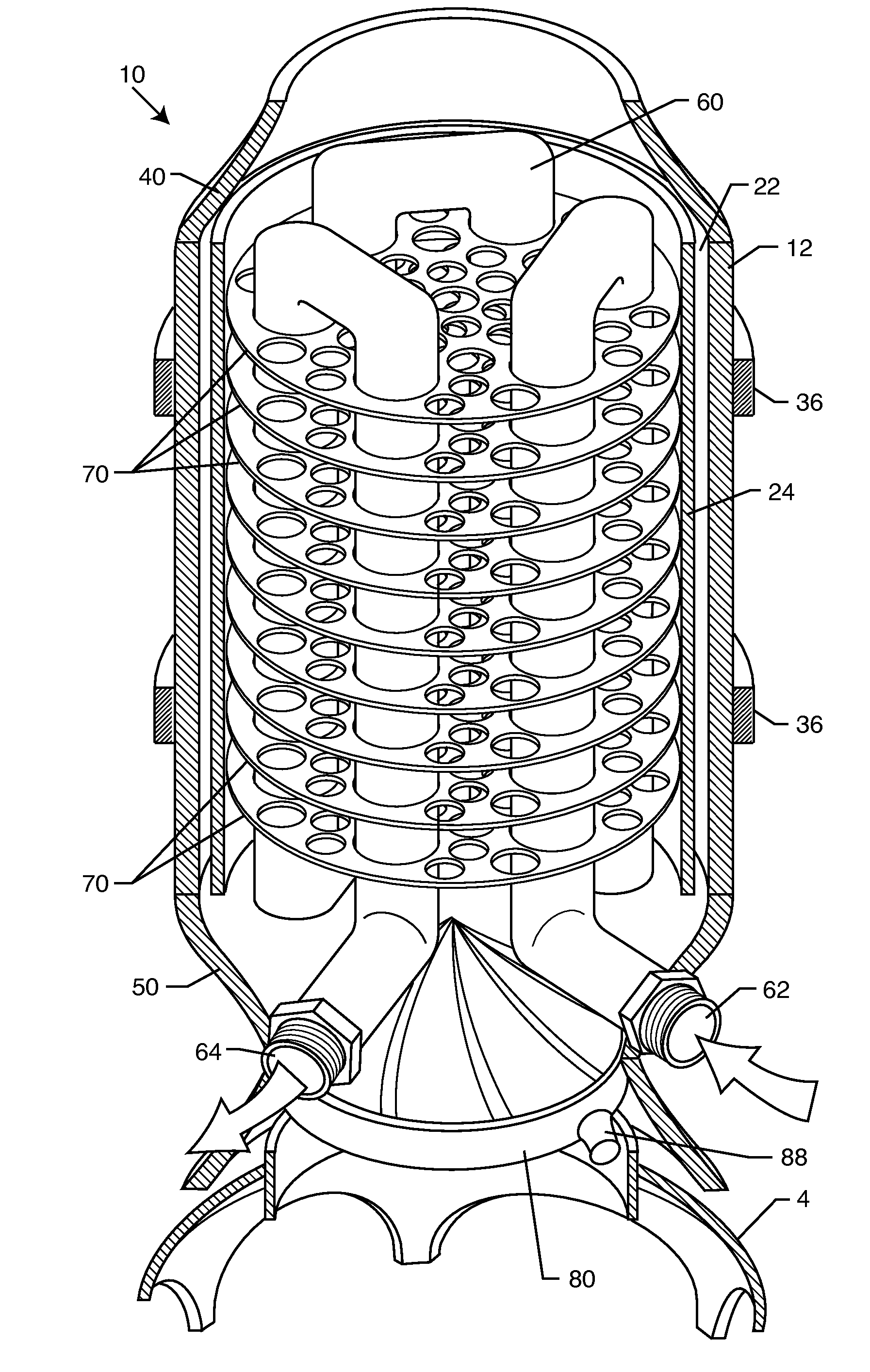
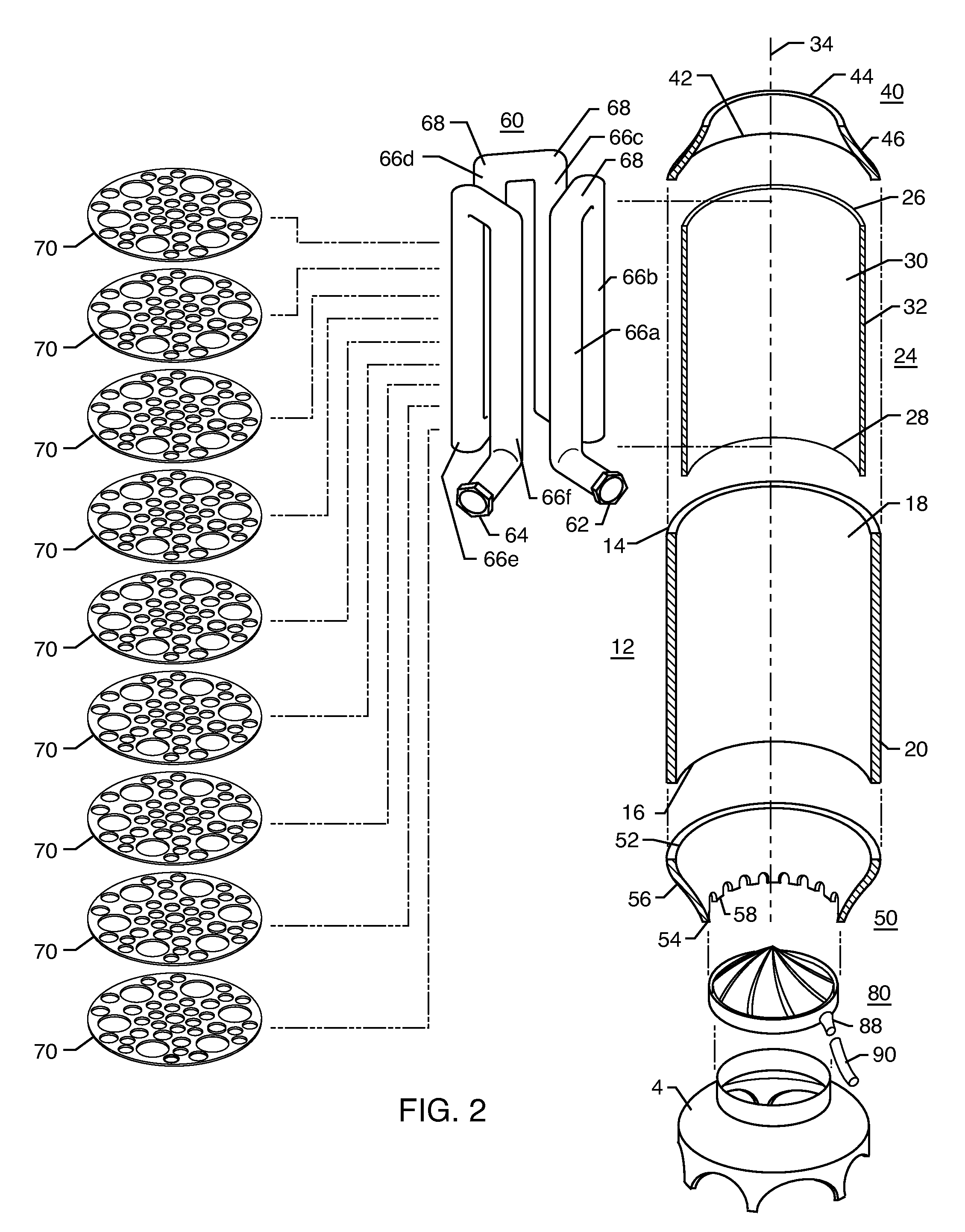
"The present invention provides an energy re-claimer that utilizes the hot gases normally vented from a water heater to preheat tap water prior to the water flowing into the water heater. The energy re-claimer is preferably mounted between the draft diverter and flue of a water heater. The energy re-claimer includes a water conducting pipe consisting of generally straight and vertical sections connected to each other by 180° returns. The size of the water conducting pipe is preferably of the same diameter as the pipe through which the cold tap water flows. The energy re-claimer also includes a plurality of generally horizontal heat exchange disks mounted inside the cylindrical wall(s) and a number of braces attached to the inner surface of the cylindrical wall(s) and the water conducting pipe for further heat exchange. A condensation collector may be installed between the exit of the water heater and the entrance of the energy re-claimer to catch any condensate that may form. The technical effects of the invention include improved energy efficiency, reduced energy waste, and improved safety."

Problems solved by technology

In some jurisdictions, the double-walled construction is mandated, because the heat in the hot gases exiting the water heater may constitute a fire hazard or an injury risk.

Method used


Image

  • Energy re-claimer
  • Energy re-claimer
  • Energy re-claimer

Examples


Embodiment Construction

[0033]In the following description of the invention, reference is made to the accompanying drawings, which form a part thereof, and in which are shown, by way of illustration, exemplary embodiments illustrating the principles of the present invention and how it may be practiced. It is to be understood that other embodiments may be utilized to practice the present invention, and structural and functional changes may be made thereto without departing from the scope of the present invention.

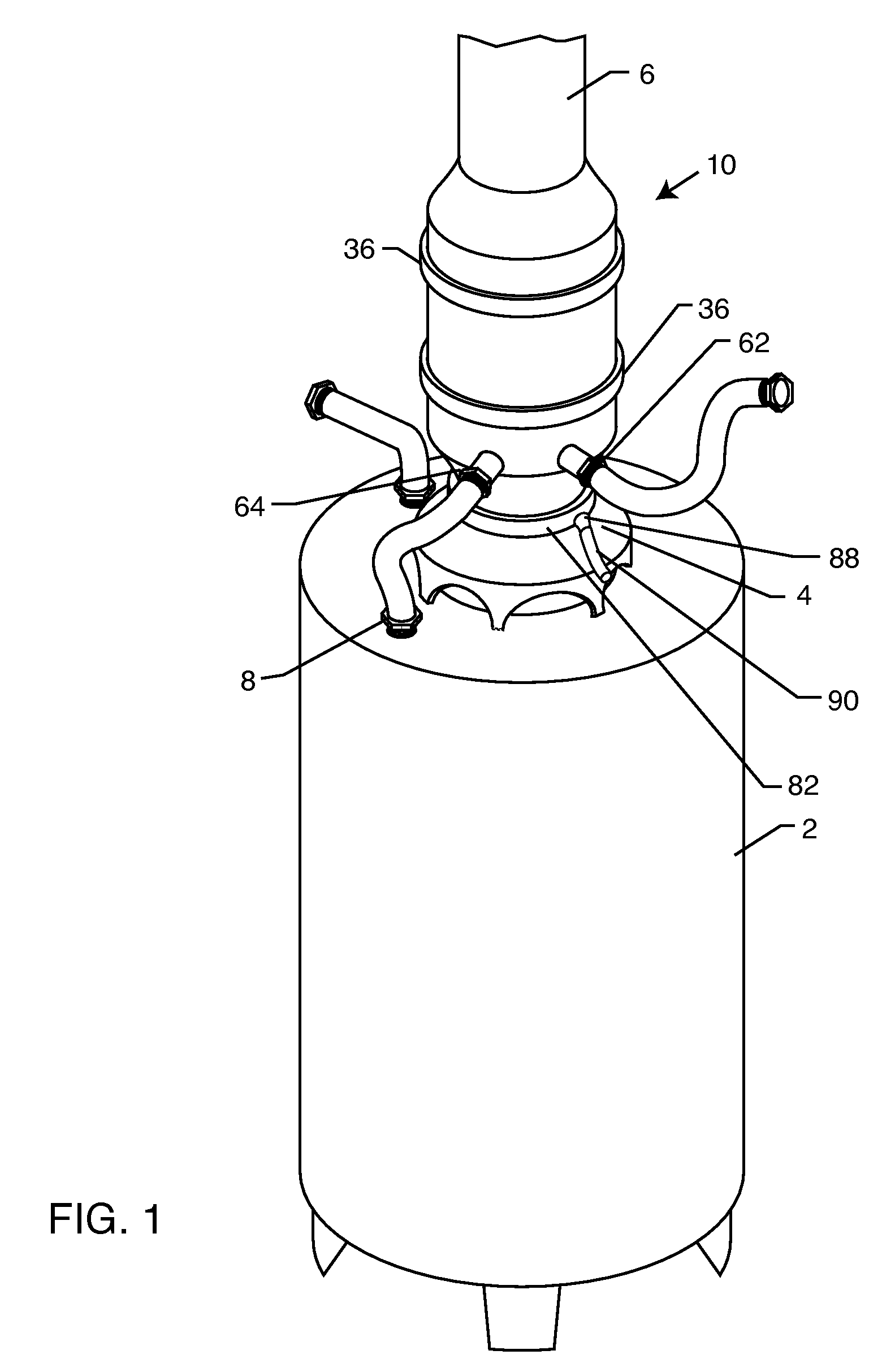
[0034]An exemplary first embodiment of an energy re-claimer is illustrated in FIGS. 1-5 and indicated by numeral 10. Energy re-claimer 10 is configured to fit on a water heater 2 between the draft diverter 4 and hot air flue 6, as best illustrated in FIG. 1. Tap water entering water heater 2 through inlet connection 8 is preheated in energy re-claimer 10 to take advantage of the energy in the hot gases exiting water heater 2 to reduce the amount of fuel needed to heat tap water for residential, comm...


PUM


Abstract

An energy re-claimer is provided for preheating water prior to the water entering a conventional residential, commercial or industrial gas water heater. The energy re-claimer is mounted on top of the water heater between the draft diverter and the hot air flue. The energy re-claimer is preferably a double wall construction that is larger in diameter than the draft diverter and hot air flue in order to allow normal passage of hot air through the system; however, a single wall construction may also be used. Tap water enters a pipe inside the double wall construction and is heated prior to being directed through the water heater. The pipe may be constructed of a number of straight lengths connected by returns or may be in the form of a single straight section connected to a coil made of connected curving sections that surround the axis of the energy re-claimer. A condensation collector may be provided between the draft diverter and the energy re-claimer to collect any condensation that may form as a result of cooling gases and prevent the condensate from falling into the water heater where it could extinguish the flame.

Description

RELATED APPLICATIONS[0001]This application claims the benefit of U.S. Provisional Patent Application No. 60 / 987,003 filed Nov. 9, 2007, entitled “Gas Water Heater Energy Re-Claimer,” and U.S. Provisional Patent Application No. 60 / 988,552 filed Nov. 16, 2007, entitled “Gas Water Heater Coil Energy Re-Claimer,” both of which are incorporated herein by reference.BACKGROUND OF THE INVENTION[0002]1. Field of the Invention[0003]The present invention relates to methods and devices for effecting heat exchange between hot gases and fluids. More particularly, the present invention relates to a heat exchange device or energy re-claimer for preheating tap water with hot gases exiting a hot water heater. The device in accordance with the present invention may be used with residential, commercial or industrial water heaters. The energy re-claimer according to the present invention includes new and novel features to enhance the efficiency of the heat exchange between hot gases and water, thus enab...

Claims


Application Information

Patent Timeline
Patent Type & Authority Patents(United States)
IPC IPC(8): F22D1/02
CPCF23J15/06F24H8/00F24H8/006F24H9/165F28D7/024F28D7/08F28D21/0007F28F1/325F28F17/005F24D12/02Y02E20/363F24D2200/18F24H9/0026Y02B30/102Y02B30/106Y02B30/14Y02B30/00Y02E20/30F24H9/17
Inventor JIMENEZ, JESUS MARTINEZ
Owner JIMENEZ JESUS MARTINEZ
Learn More