Integral fuel jet axial swirler pre-mixing preevaporated low pollution combustion-chamber

A technology of fuel injection and swirler, applied in the direction of combustion chamber, continuous combustion chamber, combustion method, etc., can solve the problems of increasing the length and weight of the engine, increasing the axial length of the head of the combustion chamber, etc., and achieve the effect of reducing the length

Inactive Publication Date: 2008-10-15
BEIHANG UNIV
View PDF2 Cites 37 Cited by
  • Summary
  • Abstract
  • Description
  • Claims
  • Application Information

AI Technical Summary

Problems solved by technology

The above-mentioned several US patents have achieved the low pollution requirements in the entire engine working range, but the fuel injection point of the main combustion

Method used


Image

  • Integral fuel jet axial swirler pre-mixing preevaporated low pollution combustion-chamber
  • Integral fuel jet axial swirler pre-mixing preevaporated low pollution combustion-chamber
  • Integral fuel jet axial swirler pre-mixing preevaporated low pollution combustion-chamber

Examples


Embodiment Construction

[0031] The present invention will be described in detail below in conjunction with the accompanying drawings and specific embodiments.

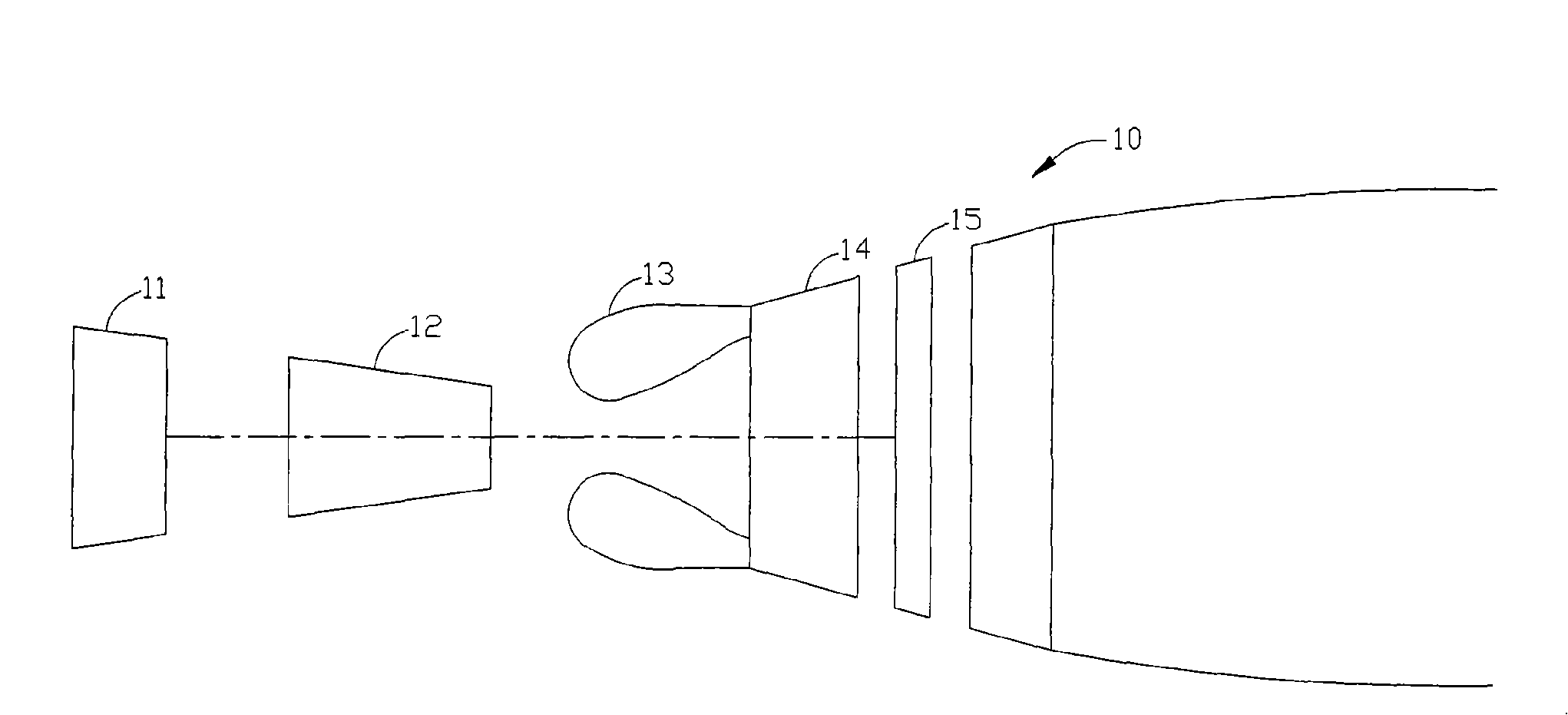
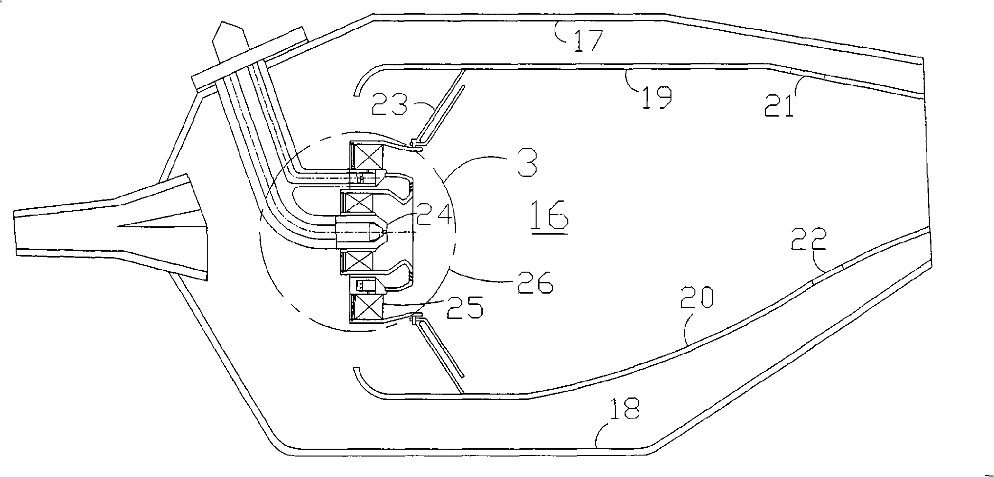
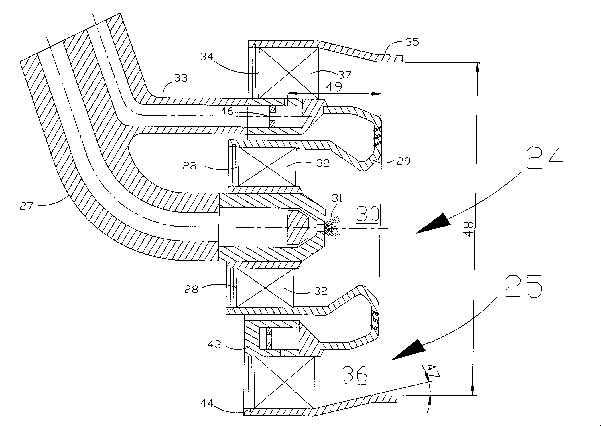
[0032] figure 1 It is a schematic diagram of an engine 10 , and the engine 10 includes a low-pressure compressor 11 , a high-pressure compressor 12 , a combustion chamber 13 , a high-pressure turbine 14 and a low-pressure turbine 15 . When the engine 10 is working, the air is compressed by the low-pressure compressor 11 and then enters the high-pressure compressor 12. The high-pressure air enters the combustion chamber 13 for combustion. Combustion, high-temperature and high-pressure gas is formed after combustion, and enters the high-pressure turbine 14 and the low-pressure turbine 15, thereby driving the turbines to do work. figure 2 is a schematic diagram of the combustion chamber 13, and the combustion chamber is a single-ring cavity structure. image 3 Yes figure 2 The enlarged view of area 3 in is the detailed structure of the comb...


PUM


Abstract

The invention discloses a combustion cavity of an integral fuel oil ejecting axial hydrocyclone with functions of premixing, pre-evaporation and low pollution. The combustion cavity has a single ring cavity structure, and consists of a combustion cavity head and a flame tube. The combustion cavity head comprises a precombustion stage positioned at the center and a main combustion stage positioned at the peripheral. The main combustion stage comprises a direct jet type air atomizer spray nozzle and a main combustion stage axial hydrocyclone. The technical proposal that the jetting of the main combustion stage fuel oil and the main combustion stage axial hydrocyclone are integrated is adopted. The main combustion stage fuel oil ejected by the direct jet type air atomizer spray nozzle enters into a main combustion stage axial hydrocyclone vane channel of a main combustion stage axial hydrocyclone vane, and the fuel oil is mixed with the rotary flow air of the main combustion stage axial hydrocyclone. A premixed oil-gas mixture enters into a combustion zone through a main combustion stage mixing cavity to be combusted. The combustion mode can effectively reduce pollutant emission in the combustion cavity and reduce the length of the combustion cavity. The combustion cavity is mainly used for an aerial engine combustion cavity, and also can be used for the combustion cavity of industrial gas turbines and ship gas turbines so as to reduce pollutant discharged into atmosphere.

Description

technical field [0001] The invention relates to a low-pollution emission combustion chamber, in particular to an integrated fuel injection axial swirler premixing pre-evaporation low-pollution combustion chamber. Background technique [0002] The main development trend of aero-engine combustors is low-pollution combustion. Aeroengine combustors must meet increasingly stringent aeroengine pollution emission standards. The currently adopted CAEP4 (Committee on Aviation Environmental Protection) standard has very strict requirements, especially for NOx pollution emission requirements, while the CAEP6 standard that will be adopted after 2008 is even more stringent. The pollution emission requirements of industrial gas turbines reach single digits—one ten-thousandth concentration emission requirements. [0003] In general, aeroengine pollutants can be divided into two categories: nitrogen oxides (NOx) due to high flame temperatures; carbon monoxide and unburned hydrocarbons (CO...

Claims


Application Information

Patent Timeline
IPC IPC(8): F23R3/58F23R3/20
Inventor 彭云晖许全宏张驰林宇震刘高恩
Owner BEIHANG UNIV
Why Eureka
Try Eureka