Stretchable anti-buckling coiled-sheet stent

a coiled sheet, stretchable technology, applied in the field of coiled sheet stents, can solve the problems of deformation of stents, unsatisfactory delivery profile, and uneven expansion of stents

Inactive Publication Date: 2012-01-10
BOSTON SCI SCIMED INC
View PDF81 Cites 10 Cited by
  • Summary
  • Abstract
  • Description
  • Claims
  • Application Information

AI Technical Summary

Benefits of technology

[0022]The stretchable elements formed in the sheet of the coiled-sheet stent may be useful to allow recoil of the stent after implantation in a blood vessel. For example, after implantation of the stent, the blood vessel may tend to contract, thereby subjecting the stent to radially compressive forces. The stretchable elements may elastically or plastically deform from the stretched shape towards the unstretched shape to substantially reduce the risk that the stent may buckle under the compressive forces, thereby allowing the stent to partially recoil under the compressive forces.
[0023]The stretchable elements may also contribute to the initial expansion of the coiled-sheet stent upon deployment, thereby facilitating withdrawal of the delivery device, such as an underlying catheter. The combination of the bias of the stretchable elements and a bias of the coiled-sheet itself to at least partially unwind may eliminate the need for subsequent further expansion of the coiled-sheet stent, as will be appreciated by those skilled in the art.

Problems solved by technology

Plastically deformable stents, however, may not expand uniformly and may not provide a desired delivery profile because of the need for a balloon on the delivery device underlying the stent.
Such stents, however, may not provide as small a delivery profile as desired and may not anchor against the wall of a vessel as securely as desired, which may lead to migration of the stent within the vessel.
A coiled-sheet stent, however, may be more rigid transverse to its longitudinal axis than tubular stents, potentially resulting in a less flexible stent, which may not be implanted as effectively in tortuous anatomical conditions.
Further, because the lattice-like structure of coiled-sheet stents is substantially nondeformable, if the stent is subjected to radially compressive forces, e.g., when the vessel wall attempts to contract, the stent may tend to buckle rather than recoil from the stress.

Method used


Image

  • Stretchable anti-buckling coiled-sheet stent
  • Stretchable anti-buckling coiled-sheet stent
  • Stretchable anti-buckling coiled-sheet stent

Examples


Embodiment Construction

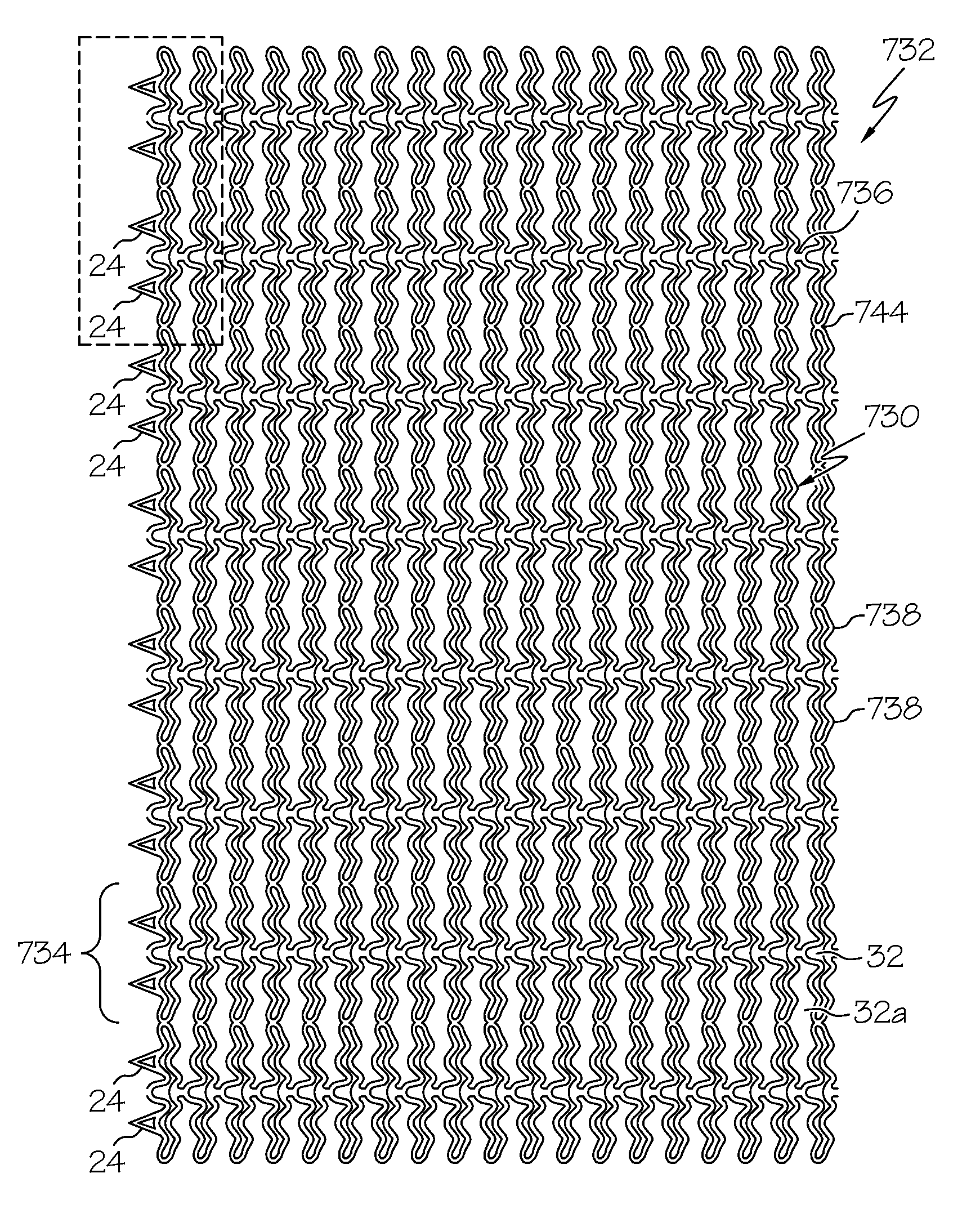
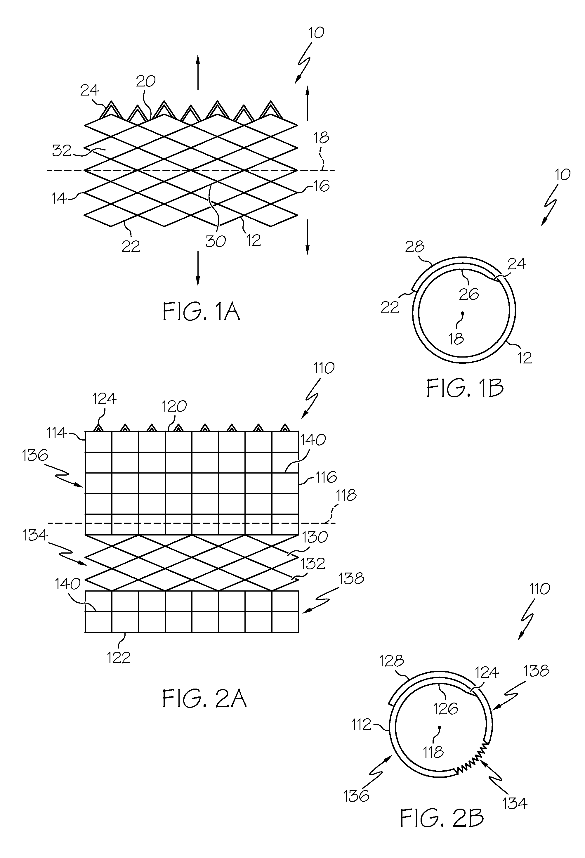
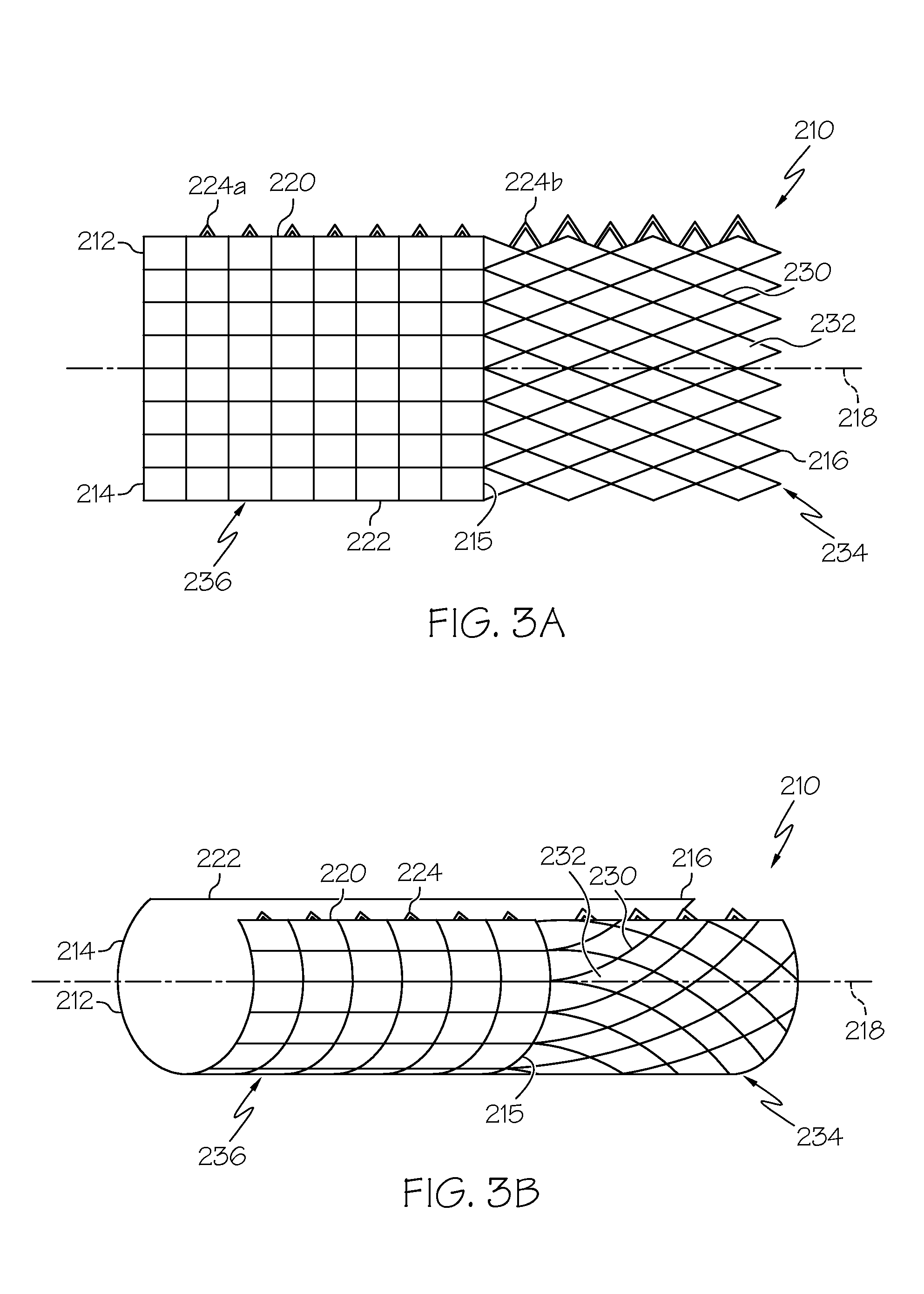
[0045]Turning now to the drawings, FIGS. 1A and 1B show a first preferred embodiment of a coiled-sheet stent 10, in accordance with one aspect of the present invention. The coiled-sheet stent 10 is formed from a substantially flat sheet 12 having first and second ends 14, 16 defining a longitudinal axis 18 therebetween. The sheet 12 also includes first and second longitudinal edges 20, 22, the first edge 20 having a plurality of fingers or teeth 24 extending therefrom substantially perpendicular to the longitudinal axis 18.

[0046]The sheet 12 also includes a plurality of stretchable elements 30 formed therein, thereby defining a multi-cellular structure capable of expanding and / or contracting in a direction substantially perpendicular to the longitudinal axis 18. Preferably, the stretchable elements 30 define a lattice-like structure providing a plurality of openings 32 for receiving the teeth 24, as described further below. The stretchable elements 30 may be elastically deformable, ...


PUM


Abstract

A stent includes a coiled-up sheet having overlapping inner and outer longitudinal sections extending parallel to a longitudinal axis thereof, and defining a periphery, the coiled-up sheet being unrollable between contracted and enlarged conditions. A plurality of stretchable elements are formed in the coiled-up sheet, the stretchable elements being expandable about the periphery between an unstretched condition to facilitate placement in a delivery device in the contracted condition and a stretched condition to facilitate expansion of the coiled-up sheet to the enlarged condition upon deployment from the delivery device. Preferably, the coiled-up sheet is biased to the enlarged condition, and the stretchable elements are biased to the stretched condition. More preferably, at least one of the biases is provided by a shape memory property of the coiled-up sheet, which is activated by exposing the stent to body temperature.

Description

[0001]This application is a Continuation-in-Part of application Ser. No. 09 / 192,977, filed Nov. 16, 1998 now U.S. Pat. No. 6,325,820.FIELD OF THE INVENTION[0002]The present invention relates generally to prostheses for implantation within body lumens, and more particularly to a coiled-sheet stent including one or more stretchable regions.BACKGROUND[0003]Tubular prostheses or “stents” are often implanted within blood vessels, for example, within the coronary and carotid arteries, for treating atherosclerotic disease which may involve one or more stenoses. Stents generally have a tubular shape capable of assuming a radially contracted condition to facilitate introduction into a patient's vasculature, and an enlarged condition for engaging the vessel wall at a treatment location. In its contracted condition, the stent may be placed on or in a delivery device, such as a catheter, percutaneously introduced into a patient's vasculature and advanced to a target treatment location. Once at ...

Claims


Application Information

Patent Timeline
Patent Type & Authority Patents(United States)
IPC IPC(8): A61F2/06A61F2/92
CPCA61F2/92A61F2/91A61F2250/0018A61F2230/008A61F2220/0016A61F2230/0054A61F2220/0008
Inventor KHOSRAVI, FARHADPATEL, HIMANSHU N.YANG, YI
Owner BOSTON SCI SCIMED INC
Why Eureka
Try Eureka