Electric motor with liquid-cooled end windings

Active Publication Date: 2012-01-10
FORD GLOBAL TECH LLC
View PDF18 Cites 26 Cited by
  • Summary
  • Abstract
  • Description
  • Claims
  • Application Information

AI Technical Summary

Benefits of technology

[0010]Advantages according to embodiments of the present disclosure may include greater and more unif

Problems solved by technology

A temperature differential between the inner side of the end windings and an outer side of the end windings limits the maximum performance and causes differential expansion and stresses thereby limiting the life of the motor.
However, the outer surface of the end windings is variable and highly convoluted as it is made of many wires pl

Method used


Image

  • Electric motor with liquid-cooled end windings
  • Electric motor with liquid-cooled end windings
  • Electric motor with liquid-cooled end windings

Examples


Example

[0018]As those of ordinary skill in the art will understand, various features of the embodiments illustrated and described with reference to any one of the Figures may be combined with features illustrated in one or more other Figures to produce alternative embodiments that are not explicitly illustrated or described. The combinations of features illustrated provide representative embodiments for typical applications. However, various combinations and modifications of the features consistent with the teachings of the present disclosure may be desired for particular applications or implementations.

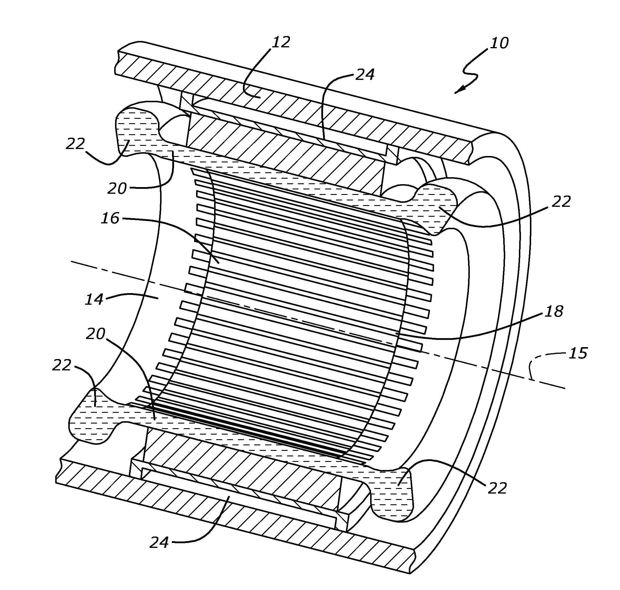
[0019]In FIG. 1, a cutaway of a portion of an electric motor 10 is shown. A housing 12 houses a stator 14, which is roughly shaped as a hollow cylinder. The stator has a plurality of laminated projections 16. The long dimension of projections 16 run parallel to the central axis 15 of stator 14 and extend inwardly toward the axis of stator 14. Between projections 16 are slots 18. Wire windin...


PUM


Abstract

Cooling of the end windings on a stator of the electric motor can be made more uniform if a physically-compliant, thermally-conductive cap is placed over the end windings. In one embodiment, a liquid coolant is sprayed on the outside of the cap. The cap serves to make the temperature more uniform in the end windings. In an alternative embodiment, a cover is placed over the cap with a coolant jacket formed between the cap and the cover. A coolant, such as transmission fluid or engine coolant, can be circulated in the coolant jacket.

Description

BACKGROUND[0001]1. Technical Field[0002]The present disclosure relates to cooling of electric motors.[0003]2. Background Art[0004]To obtain good performance and long life of an electric motor, cooling is essential. In some motors, a fluid is sprayed onto winding ends of the coil to provide a higher heat transfer rate than possible with forced air convection. It is important to attempt to uniformly spray the end windings. In one example shown, oil is sprayed from the center, i.e., from a center-mounted rotor that has an oil supply, toward the windings. A temperature differential between the inner side of the end windings and an outer side of the end windings limits the maximum performance and causes differential expansion and stresses thereby limiting the life of the motor. In one alternative, a heat sink is placed over the ends of the end windings to even out the temperature variation. However, the outer surface of the end windings is variable and highly convoluted as it is made of ...

Claims


Application Information

Patent Timeline
IPC IPC(8): H02K9/00H02K9/08
CPCH02K3/24H02K9/19
Inventor BERHAN, MICHAEL TEKLETSION
Owner FORD GLOBAL TECH LLC
Why Eureka
Try Eureka