Supercharge Your Innovation With Domain-Expert AI Agents!

Lamp ballast and an illumination apparatus

a technology of illumination apparatus and ballast, which is applied in the direction of electric variable regulation, process and machine control, instruments, etc., can solve the problems of undue electric stress of incandescent lamps, undue electric stress shortening etc., to prevent inrush current and prolong the life of incandescent lamps

Inactive Publication Date: 2012-01-10
MATSUSHITA ELECTRIC WORKS LTD
View PDF6 Cites 5 Cited by
  • Summary
  • Abstract
  • Description
  • Claims
  • Application Information

AI Technical Summary

Benefits of technology

"The present invention provides a lamp ballast that can supply proper electric power to both discharge lamps and incandescent lamps without applying a high voltage pulse. The lamp ballast includes a DC-DC converter, an inverter, a starting circuit, a controller, and a comparator. The controller controls the DC-DC converter and the inverter to provide a variable DC voltage and an AC power to the lamp load. The comparator compares the DC voltage with a predetermined threshold and sends a signal to the controller. The controller selects the appropriate lighting program based on the signal and controls the current output from the DC-DC converter accordingly. This prevents a high inrush current and extends the life of the incandescent lamp. The lamp ballast is able to supply the proper power to the connected lamp load and has a detection mode for identifying the type of lamp connected."

Problems solved by technology

This causes the incandescent lamp to suffer from an undue electric stress.
The undue electric stress shortens a life of the incandescent lamp.

Method used


Image

  • Lamp ballast and an illumination apparatus
  • Lamp ballast and an illumination apparatus
  • Lamp ballast and an illumination apparatus

Examples


Embodiment Construction

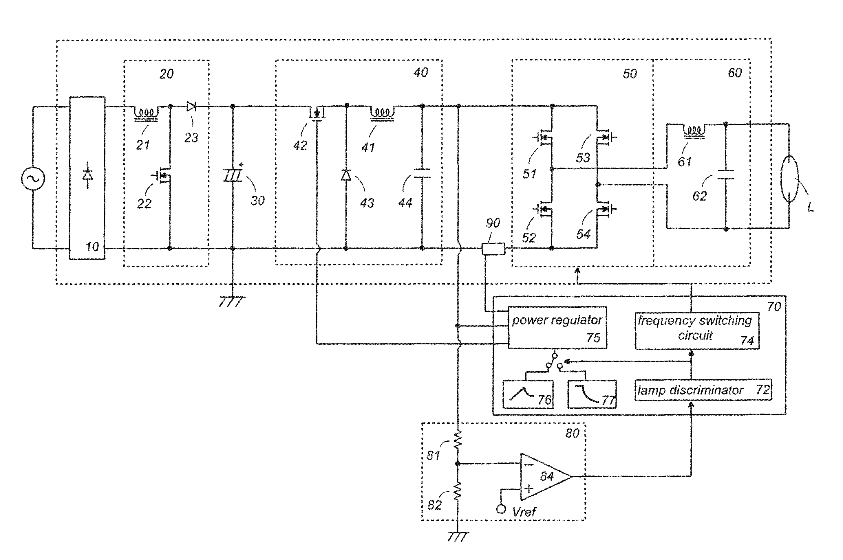
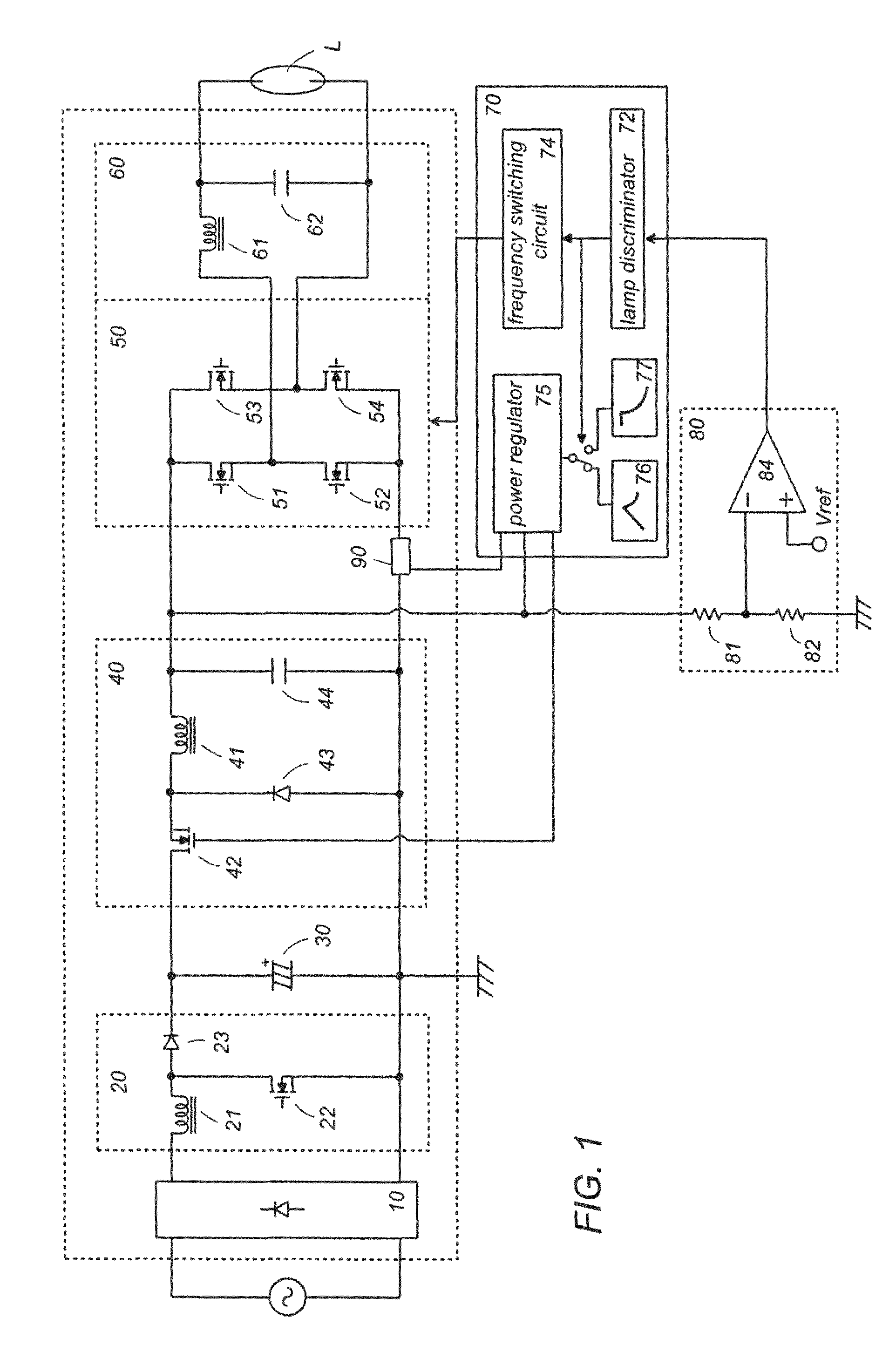
[0017]Referring to attached drawings, a lamp ballast in accordance with a preferred embodiment of the present invention is explained. The lamp ballast is designed to turn on a discharge lamp such as a high intensity discharge lamp, and an incandescent lamp such as a halogen lamp. As shown in FIG. 1, the lamp ballast includes a diode bridge 10 for full-wave rectification of an AC power source, a smoothing capacitor 30 connected across the diode bridge 10 through a power factor correction (power factor improvement) circuit 20, a DC-DC converter 40 configured to output a DC voltage by use of the smoothing capacitor 30 as a power source, a inverter 50 configured to convert the DC voltage output from the DC-DC converter 40 into an AC power, and a controller 70 configured to control the DC-DC converter 40 and the inverter 50. The power factor correction circuit 20 configures a boost converter (a step-up chopper) having an inductor 21, a switching device 22, and a diode 23. The inductor 21...


PUM


Abstract

A lamp ballast capable of lighting a discharge lamp and an incandescent lamp each at an optimum condition. The lamp ballast has a DC-DC converter, an inverter that converts an output of DC-DC converter into an AC power for applying the same to a lamp load, a starting circuit generating a high voltage pulse from the AC power to provide the same to the lamp load, and a controller that controls the DC-DC converter and the inverter to provide a variable DC voltage and the AC power of variable frequency. The controller has a starting mode of operating the inverter at a starting frequency to generate the high voltage, and a lighting mode of operating the inverter at a lighting frequency lower than the starting frequency. The controller has a detection mode of causing the DC-DC converter to output a detection voltage of a predetermined level prior to the starting mode, a discharge lamp lighting program of operating, after the detection mode, the inverter in the starting mode and subsequently in the lighting mode, and an incandescent lamp lighting program of operating, after the detection mode, the inverter in the lighting mode without through the starting mode. When the detection voltage exceeds a predetermined threshold, the controller selects the discharge lamp lighting program, and otherwise selects the incandescent lamp lighting program. When the incandescent lamp is connected, the ballast turns on the incandescent lamp without applying a high voltage pulse so as to avoid lowering of the lamp life.

Description

TECHNICAL FIELD[0001]The present invention is directed to a lamp ballast capable of selectively operating a discharge lamp such as a high intensity discharge lamp and an incandescent lamp such as a halogen lamp, and an illumination apparatus employing the lamp ballast.BACKGROUND ART[0002]Japanese Patent Publication JP2002-352970 A discloses a lamp ballast for a high intensity discharge lamp which includes a lamp discriminating means so as not to supply an excessive power upon being accidentally connected to an incandescent lamp such as a halogen lamp. The lamp ballast includes a DC-DC converter providing a variable DC voltage, an inverter converting the output voltage from the DC-DC converter into the AC power to be applied to a lamp load, a starting circuit for generating a high voltage pulse out of the output voltage from the inverter and applying the high voltage pulse to the lamp load, and a control circuit for varying the output voltage from the DC-DC converter. The lamp discri...

Claims


Application Information

Patent Timeline
Patent Type & Authority Patents(United States)
IPC IPC(8): G05F1/00
CPCH02M1/36H05B41/36H05B41/2886H05B41/2887H05B39/045H02M2001/007H02M1/007
Inventor GORIKI, TAKESHIYUFUKU, AKIRA
Owner MATSUSHITA ELECTRIC WORKS LTD
Features
  • R&D
  • Intellectual Property
  • Life Sciences
  • Materials
  • Tech Scout
  • Unparalleled Data Quality
  • Higher Quality Content
  • 60% Fewer Hallucinations
Learn More