Braking function for brushless DC motor control

a brushless dc motor and braking function technology, applied in the direction of motor/generator/converter stopper, dynamo-electric converter control, stopping arrangement, etc., can solve the problems of reverse motor spinning, not adapting well to changing motor characteristics,

Active Publication Date: 2012-01-10
ALLEGRO MICROSYSTEMS INC
View PDF48 Cites 17 Cited by
  • Summary
  • Abstract
  • Description
  • Claims
  • Application Information

AI Technical Summary

Problems solved by technology

A drawback to the fixed time approach is that is does not adapt well to changing motor characteristics and can allow reverse motor spinning to occur.

Method used


Image

  • Braking function for brushless DC motor control
  • Braking function for brushless DC motor control
  • Braking function for brushless DC motor control

Examples


Embodiment Construction

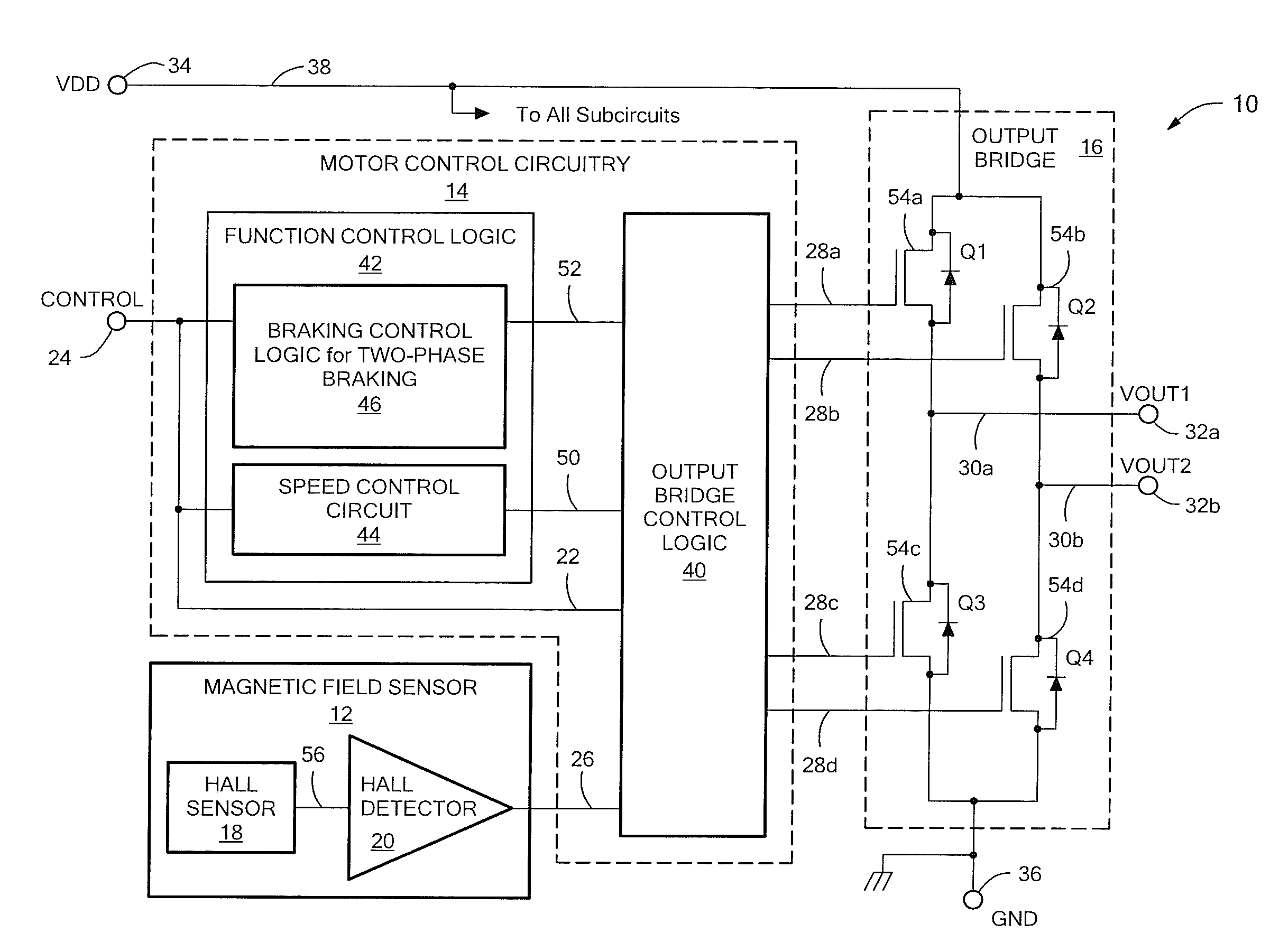
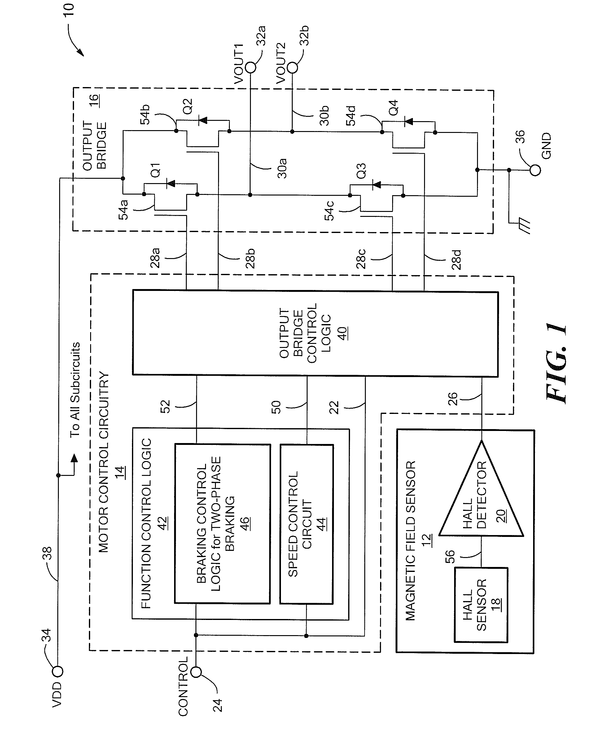
[0016]Referring to FIG. 1, an exemplary embodiment of a motor control device (or circuit) 10 for controlling rotational movement of an external single-coil brushless DC motor (BLDC) is shown. The motor control device 10 includes a magnetic field sensor 12, motor control circuitry 14 and an output structure in the form of an output bridge 16. The output bridge 16 serves as a motor driver circuit. The magnetic field sensor 12 may be any magnetic field sensing device, for example, one that includes a Hall sensor 18 and detector 20, as shown.

[0017]Still referring to FIG. 1, the motor control circuitry 14 receives as a first input signal 22 a control signal generated by an external source via an input (or control input, “CONTROL”) terminal 24. It receives the output of the magnetic field sensor 12 as a second input signal 26. The circuitry 14 provides output control signals 28a-28d to the output bridge 16, which converts them to output voltages 30a and 30b, made available at correspondin...


PUM


Abstract

A motor control circuit that features a smart, two-phase braking operation is presented. The motor control circuit includes a motor drive circuit to apply a brake current to a coil of an external motor for active braking of the motor. The motor control circuit further includes a braking control circuit, coupled to the motor drive circuit and responsive to an externally generated control signal, to control the active braking by the motor drive circuit so that the active braking occurs in two phases. The two phases include a first phase that includes a first portion of the active braking and a second phase that includes back electromotive force (BEMF) voltage sensing and a second portion of the active braking.

Description

CROSS-REFERENCE TO RELATED APPLICATIONS[0001]Not applicable.STATEMENT REGARDING FEDERALLY SPONSORED RESEARCH[0002]Not applicable.FIELD OF THE INVENTION[0003]This invention relates generally to motor control and, more particularly, to braking motor control for single-coil brushless DC motors.BACKGROUND OF THE INVENTION[0004]A brushless DC (BLDC) motor is braked by generating a negative torque which slows the rotation of the motor. A periodic determination is performed to detect when the application of the braking torque should be discontinued. It may determine, for example, when a specified time interval has elapsed (a fixed braking time approach) or a sensed motor speed has achieved a desired threshold value (a speed sensing approach). One prior technique for braking uses the back electromotive force (EMF) voltage induced in a coil of the motor. This “passive braking” generates a negative torque by shorting a coil. Another braking technique that has been used in the past is “active ...

Claims


Application Information

Patent Timeline
Patent Type & Authority Patents(United States)
IPC IPC(8): H02K7/10
CPCH02P6/24
Inventor MILESI, ALEJANDRO G.UBERTI, BRUNO L.
Owner ALLEGRO MICROSYSTEMS INC
Why Eureka
Try Eureka