
Electromagnetic lock monitoring system

a technology of electronic lock and monitoring system, applied in the field of electronic lock, can solve the problems of only monitoring half of the actual magnetic field available, and the magnetic field directly adjacent to the hall effect device is actually monitored

Active Publication Date: 2012-01-10
HANCHETT ENTRY SYST
View PDF10 Cites 11 Cited by
  • Summary
  • Abstract
  • Description
  • Claims
  • Application Information

AI Technical Summary

Benefits of technology

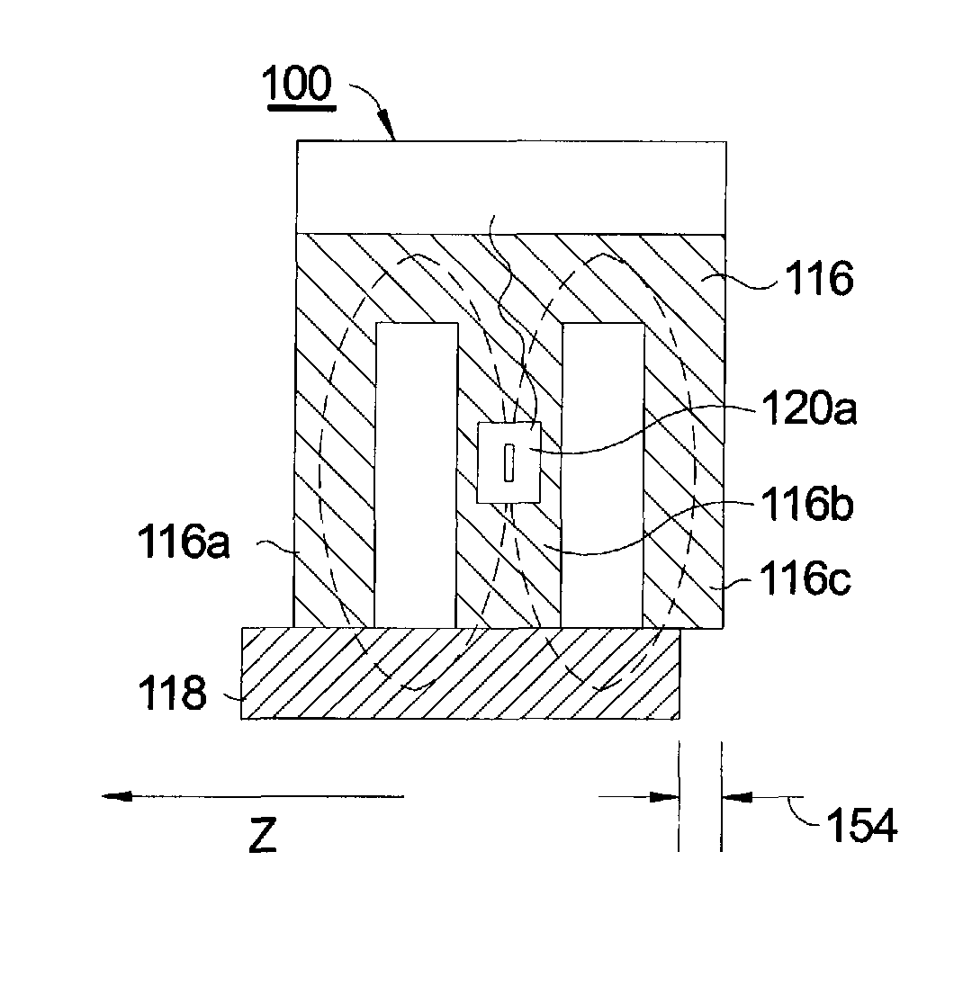
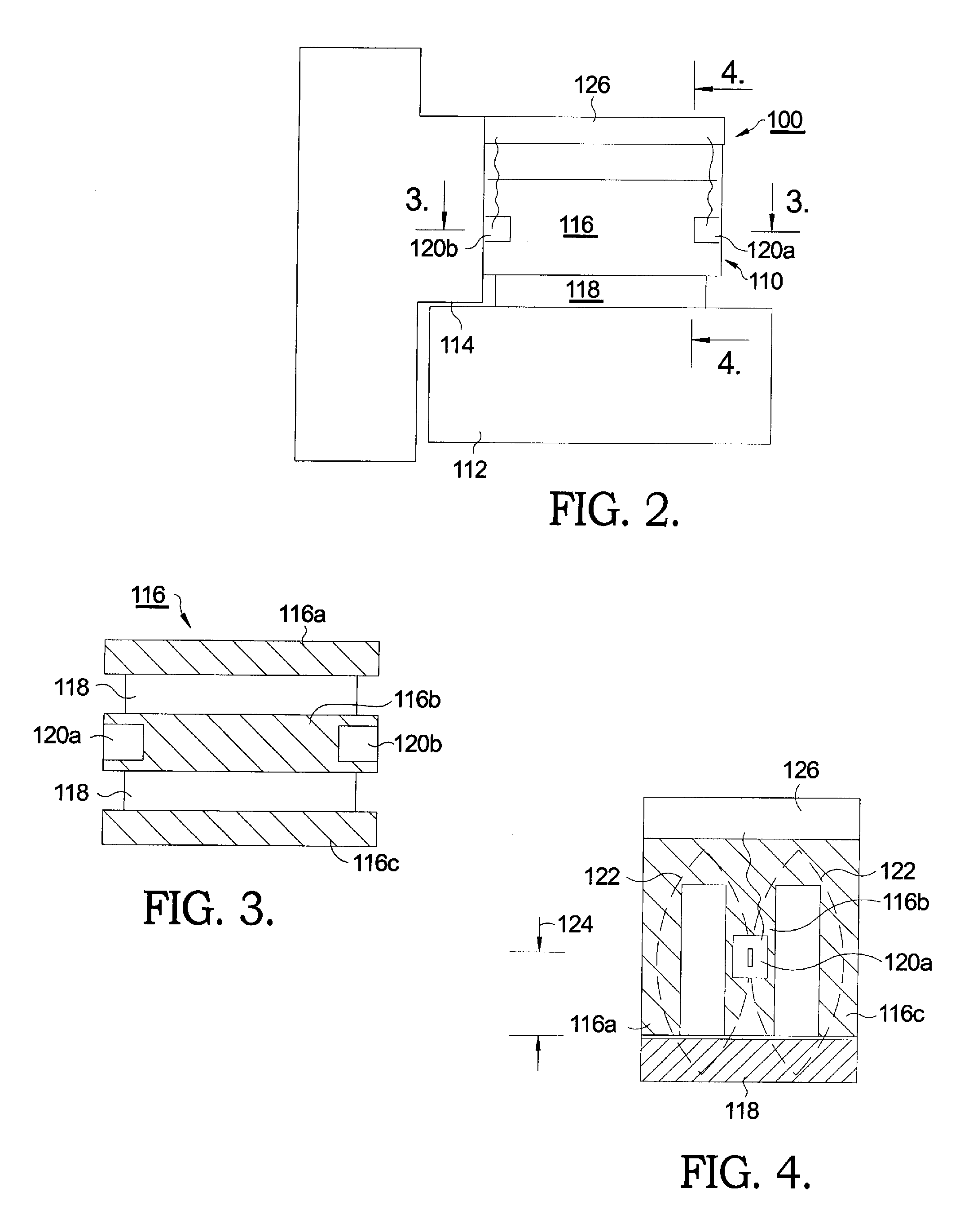
The present invention is an electromagnetic lock monitoring system that uses Hall Effect devices to monitor the strength of the magnetic field created when the lock is properly closed. The system effectively covers the complete contact surface between the electromagnet and the armature plate. The Hall Effect devices are connected in series with a relay and are placed at the point of maximum flux density within the E-shaped electromagnetic core. If the magnetic flux falls below a preset limit, the relay drops out, triggering an alarm that may be sonic, electronic, or visual. The system can detect lock misalignments as small as 0.25 inch.

Problems solved by technology

A significant problem with such a prior art system is that only the magnetic field immediately adjacent the Hall Effect device is actually monitored.
Furthermore, use of a single Hall Effect device may lead to monitoring only half of the actual magnetic field available, as there are two overlapping magnetic fields in operation with a typical E-shaped magnetic core used in many prior art electromagnetic locks.

Method used


Image

  • Electromagnetic lock monitoring system
  • Electromagnetic lock monitoring system
  • Electromagnetic lock monitoring system

Examples


Embodiment Construction

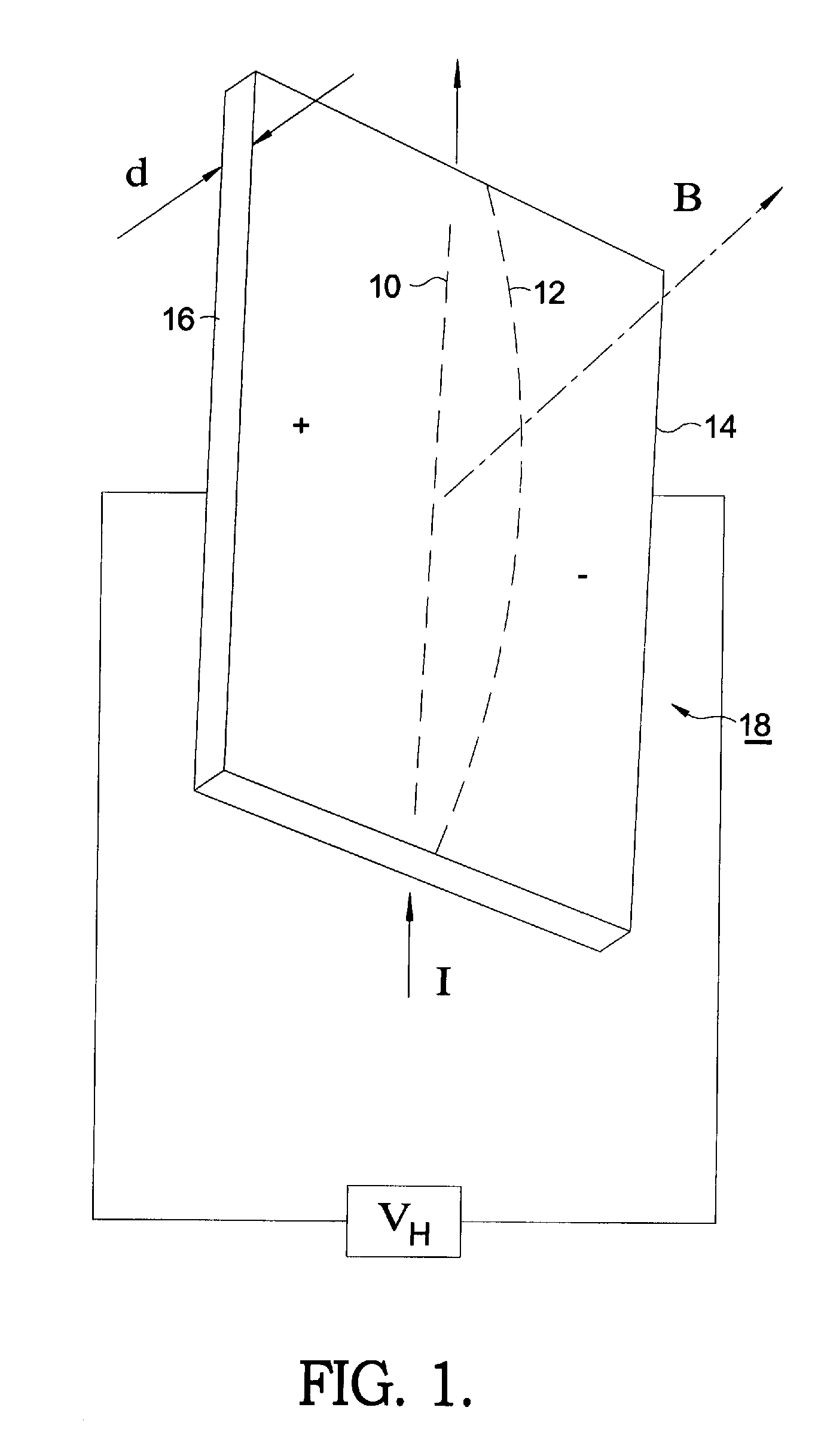
[0020]Referring to FIG. 1, the Hall effect comes about due to the nature of the current in a conductor. Current I consists of the movement of many small charge-carrying “particles” (typically, but not necessarily, electrons). Moving charges experience a force, called the Lorentz Force, when a magnetic field B is present that is not parallel to their motion. When such a magnetic field is absent, the charges follow an approximately straight ‘line of sight’ path 10. However, when a perpendicular magnetic field B is applied, their path is curved 12 so that moving charges accumulate on one face 14 of the material. This leaves equal and opposite charges exposed on the other face 16, where there is a scarcity of mobile charges. The result is an asymmetric distribution of charge density across the Hall element 18 that is perpendicular to both the ‘line of sight’ path 10 and the applied magnetic field B. The separation of charge defines an electric field that opposes the migration of further...


PUM


Abstract

An electromagnetic lock monitoring system for monitoring the strength of a magnetic field in an electromechanical lock which is created when a steel armature plate is closed against an electromagnet. The system utilizes dual Hall Effect devices positioned in such a way that both ends of the electromagnet and both magnetic fields are monitored, and that the resulting monitoring effectively covers the complete contact surface between the electromagnet and the armature plate. Preferably, the Hall Effect devices are disposed in series at the point of maximum flux density within the center element of an E-shaped electromagnetic core, at opposite ends of the core. If the magnetic flux is below a preset limit, a relay also in series drops out, triggering an alarm which may be sonic, electronic, and / or visual, as is known in the prior art.

Description

RELATIONSHIP TO OTHER APPLICATIONS AND PATENTS[0001]The present application claims priority from U.S. Provisional Patent Application, Ser. No. 61 / 010,557, filed Jan. 8, 2008.TECHNICAL FIELD[0002]The present invention relates to electromagnetic locks; more particularly, to apparatus for monitoring the lock status of electromagnetic locks; and most particularly, to an improved electromagnetic lock monitoring system employing a plurality of Hall Effect sensors.BACKGROUND OF THE INVENTION[0003]Electromagnetic locks for securing doors or gates are well known in the prior art. In a typical installation, a magnetically-susceptible plate is mounted on a door, and an electromagnet is mounted on a door jamb or gate post. When the electromagnet is energized, is in contact with the plate, and the door is closed, the plate becomes an armature for the electromagnet. Magnetic flux passes between the electromagnet and the armature, attracting the armature to the electromagnet and thus providing a m...

Claims


Application Information

Patent Timeline
Patent Type & Authority Patents(United States)
IPC IPC(8): E05B45/06
CPCE05C19/166G01R33/072Y10T70/7062
Inventor HUNT, ROBERT C.KING, JONATHAN
Owner HANCHETT ENTRY SYST
Learn More