Modular high-power drive stack system and method

a high-power drive and modular technology, applied in the direction of motor/generator/converter stopper, dynamo-electric converter control, coupling device connection, etc., can solve the problems of limiting the configurability of the device, removing, repairing, and installing the device, and time-consuming

Inactive Publication Date: 2012-01-10
PARKER INTANGIBLES LLC
View PDF17 Cites 19 Cited by
  • Summary
  • Abstract
  • Description
  • Claims
  • Application Information

AI Technical Summary

Problems solved by technology

There are a variety of drawbacks associated with such prior art devices.
Many such devices are not pluggable and / or removably insertable, which makes removing, repairing, and installing the device difficult and time consuming.
In such case, the device has its own controller embedded and custom input / output connections, which substantially limits the configurability of the device(s).

Method used


Image

  • Modular high-power drive stack system and method
  • Modular high-power drive stack system and method
  • Modular high-power drive stack system and method

Examples


Embodiment Construction

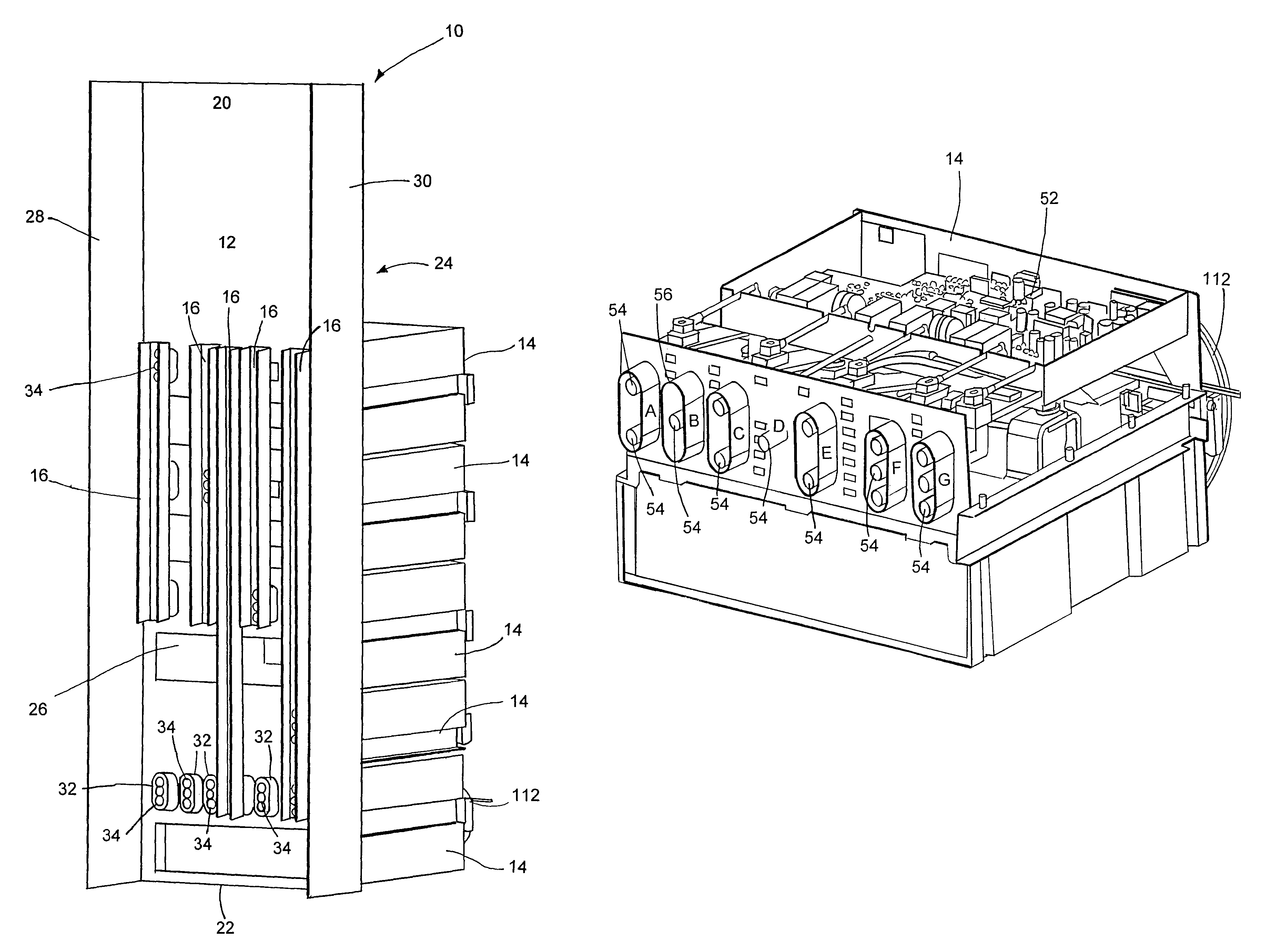
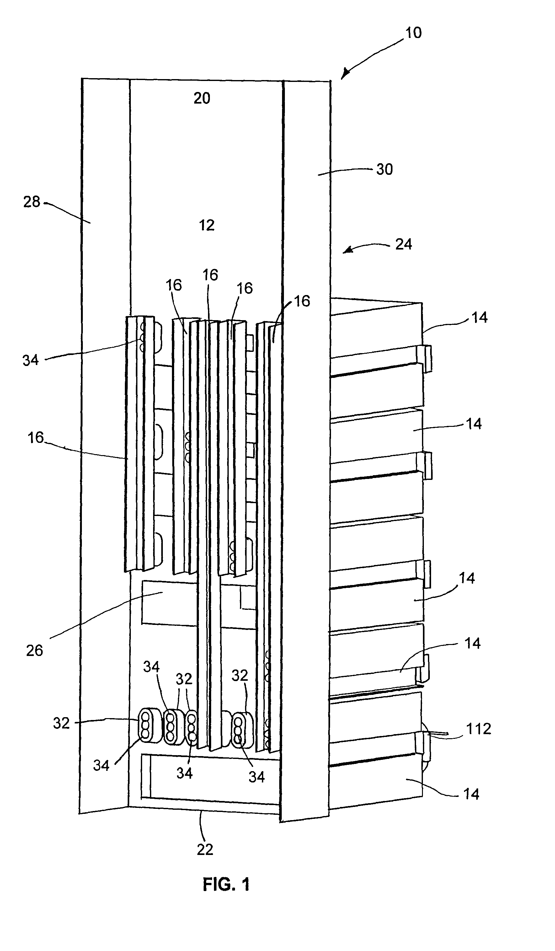
[0027]Referring now in detail to the drawings and initially to FIG. 1, an exemplary high power drive stack system 10 according to the invention is illustrated. The high power drive stack 10 includes a common support structure 12, a plurality of power electronic modules 14 and a plurality of couplers 16. As used herein, the phrase “high power” means a circuit having a voltage of more than 50 V AC or 120 V DC or a current above 50 Amps.

[0028]The common support structure 12 may be any suitable storage structure. For example, the common support structure 12 may be a rack storage system, as shown in FIG. 1. The common support structure 12 can be fabricated from steel or aluminum (or any other suitable material) and may optionally include parallel vertical rails or rack rails for storing one or more components (e.g., modules 14). The common support structure 12 generally includes a top 20, bottom 22, front 24, rear 26 and sides 28 and 30. The common support structure is generally configur...


PUM


Abstract

A power drive stack system comprises a series of power electronic modules, each one of the modules containing power components and module contacts electrically and mechanically aligned for building a portion of a complete AC / DC drive stack. The modules utilize a common set of circuit connection points that are matched to a common set of physical connection points. The modules can be plugged together like building blocks to form a large variety of AC / DC drive stacks that can be tailored to meet an exact system requirement. The drive stack may be used in conjunction with a controller to adjust the torque and speed of an AC / DC electric motor.

Description

RELATED APPLICATIONS[0001]This application claims the benefit of U.S. Provisional Application No. 60 / 746,293 filed May 3, 2006, which is incorporated herein by reference.FIELD OF THE INVENTION[0002]The invention herein described relates to power electronic modules that can be connected together to form a variety of configurations of power electronic alternating current (AC) or direct current (DC) motor drive stacks, and more generally to a system and method for a modular motor drive stack and / or uninterruptible power supplies that are pluggable and scalable for use in a variety of applications.BACKGROUND[0003]High-power drive stacks are used in a wide variety of applications. Such applications include for example, driving a motor, regenerating energy from a windmill or other renewable power source back to a distribution line, braking systems for large inertia objects (e.g., large wheel), etc.[0004]A conventional high power drive stack is a monolithic unit that typically includes ele...

Claims


Application Information

Patent Timeline
Patent Type & Authority Patents(United States)
IPC IPC(8): H02B13/02H02P27/04H01R13/64H05K7/20
CPCH05K7/1432H05K7/14325
Inventor HOWES, JEREMYLEVETT, DAVIDFROEB, JOHN
Owner PARKER INTANGIBLES LLC
Why Eureka
Try Eureka