Method for determining fuel injection on-time in a gaseous-fuelled internal combustion engine

a technology of gaseous fuel injection and internal combustion engine, which is applied in the direction of electric control, instruments, brake systems, etc., can solve the problems of insufficient economic, practical and reliable large-volume commercial use, high fuel mass flow rate for a given gaseous fuel injection time, and high cost of instrumentation. achieve the effect of accurate metered

Active Publication Date: 2012-01-10
WESTPORT FUEL SYST CANADA INC
View PDF13 Cites 59 Cited by
  • Summary
  • Abstract
  • Description
  • Claims
  • Application Information

AI Technical Summary

Benefits of technology

[0017]The present method can further comprise correcting the injection on-time by applying a correction factor that is retrieved by the controller from a plurality of look-up tables. The method then comprises storing in a plurality of predetermined correction factor look-up tables correction factor values retrievable as a function of gaseous fuel rail pressure and fuelling amount, with each look-up table corresponding to a value for a fourth parameter Q that can be one of the parameters that correlates to in-cylinder pressure which is different than third parameter P. Input data indicating values for fourth parameter Q are sent to the controller which then identifies from the plurality of predetermined correction factor look-up tables two correction factor look-up tables which correspond to fixed values of fourth parameter Q that are closest in value to that of the fourth parameter in the input data. The controller determines the desired correction factor by interpolating between the two correction factor look-up tables identified in the previous step. Fourth parameter can be one of: timing for start of injection, intake manifold pressure and compression pressure. The controller can use different interpolation methods for retrieving the desired correction factor such as polynomial interpolation or spline interpolation or simpler interpolation methods such as linear interpolation or piecewise constant interpolation.

Problems solved by technology

That is, for a gaseous fuel injection valve, higher in-cylinder pressures can increase the valve opening speed, which can result in a higher fuel mass flow rate for a given gaseous fuel injection time.
While instrumentation exists to measure in-cylinder pressure directly, such instrumentation is expensive, more suited to research purposes and is not considered economical, practical and reliable enough for large-volume commercial use.
The problem with adding more parameters is that this can add to the complexity of the determination of such adjustments, which need to be made quickly in real-time to be practical and effective, given the speed at which engines operate.

Method used


Image

  • Method for determining fuel injection on-time in a gaseous-fuelled internal combustion engine
  • Method for determining fuel injection on-time in a gaseous-fuelled internal combustion engine
  • Method for determining fuel injection on-time in a gaseous-fuelled internal combustion engine

Examples


Embodiment Construction

)

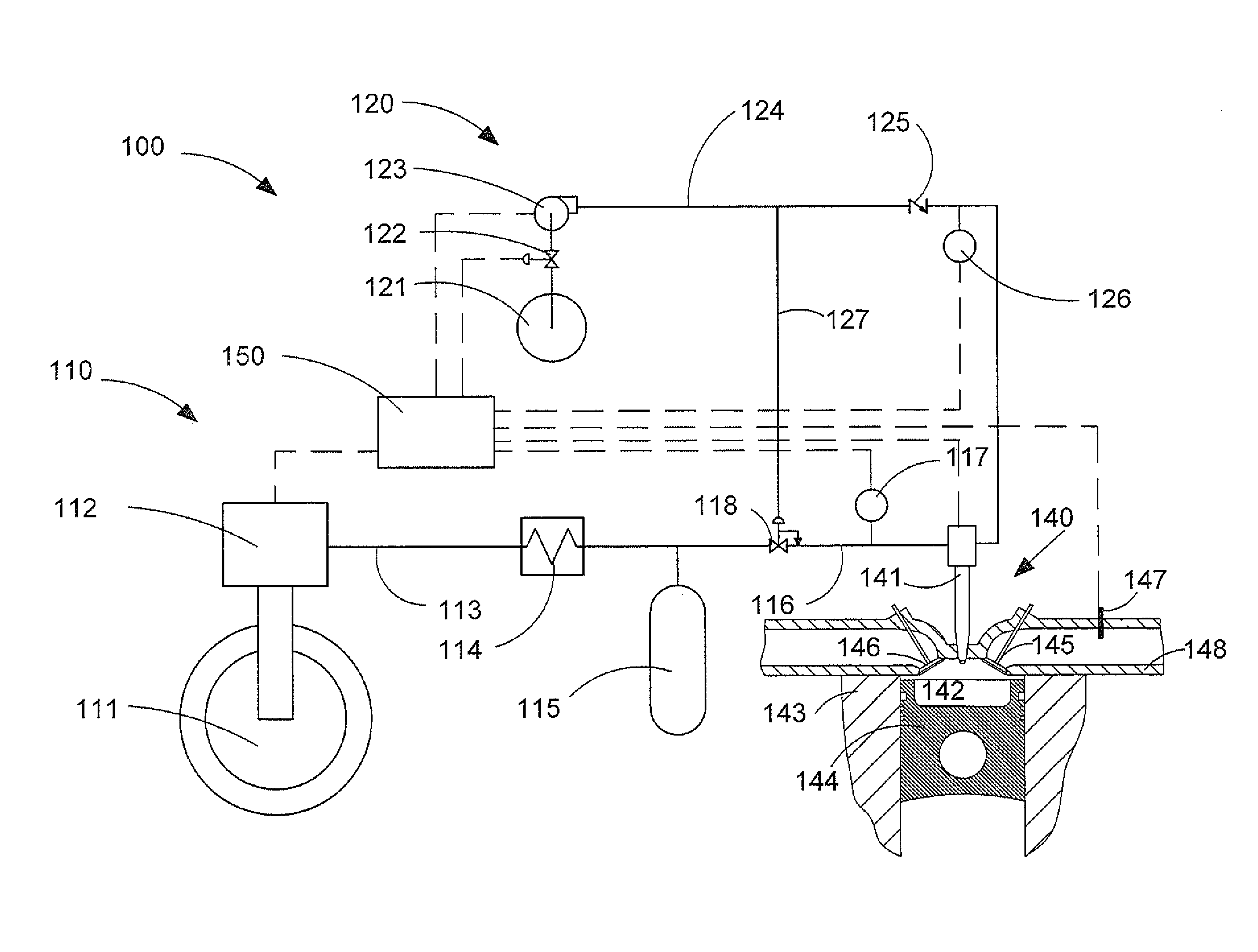
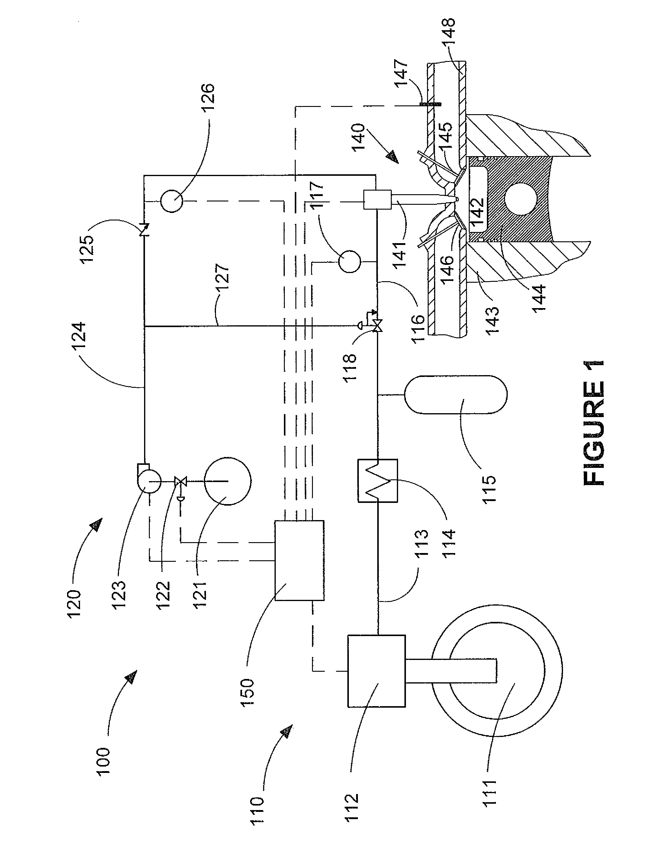
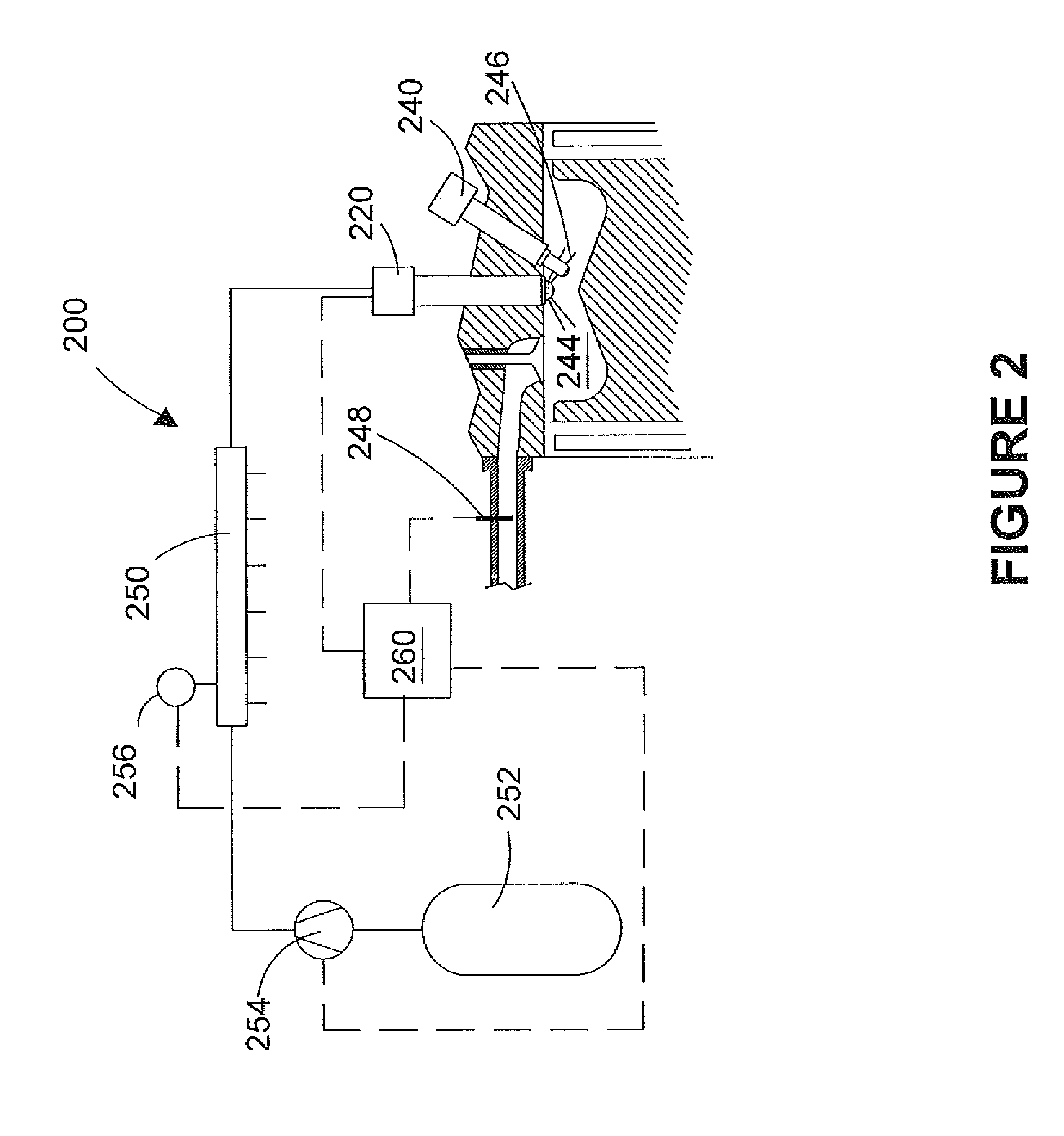
[0023]FIGS. 1 and 2 show schematic views of two engine systems for injecting a gaseous fuel directly into the combustion chamber of an internal combustion engine. Herein “direct injection” is used to refer to the injection of fuel directly into the combustion chamber of an internal combustion engine, which is an approach that is technically distinct from engines that inject fuel into an engine's intake manifold or into the intake ports on the manifold side of the engine's intake valves. The schematic views shown in FIGS. 1 and 2 are not to scale, with some parts shown larger relative to the other parts to better illustrate their function.

[0024]When substituting diesel with cleaner burning gaseous fuels such as natural gas if one were to rely upon compression ignition alone, much higher temperatures and pressures for auto-igniting the gaseous fuel would be required. A solution to this problem, which allows substantially the same compression ratios and the major components of diesel ...


PUM


Abstract

A method and apparatus determine the fuel injection on-time to accurately meter fuel injected directly into the combustion chamber of a gaseous fuelled internal combustion engine. The fuel injection on-time is determined by interpolating between values retrieved from two of a plurality of predetermined look-up tables, which each define fuel injection on-time as a function of gaseous fuel rail pressure and fuelling amount. Each table corresponds to a fixed value of a third parameter that correlates to in-cylinder pressure.

Description

FIELD OF THE INVENTION[0001]The present invention relates to a method and apparatus for determining the fuel injection on-time in a gaseous-fuelled internal combustion engine such that the amount of fuel being injected into the combustion chamber of the engine is accurately metered. “On-time” is defined herein to mean the time that an injection valve is in an open position, when fuel is being injected into a combustion chamber through the injection valve. On-time is sometimes referred to by others as “pulse width”.BACKGROUND OF THE INVENTION[0002]Presently, many internal combustion engines are compression ignition engines fuelled by diesel fuel. In such engines, liquid fuel is injected directly into the combustion chamber so the fuel must be pumped to an injection pressure greater than the pressure inside the combustion chamber when the fuel is being introduced, to overcome the so-called “in-cylinder pressure”. In a diesel engine, the peak in-cylinder pressure is typically less than...

Claims


Application Information

Patent Timeline
Patent Type & Authority Patents(United States)
IPC IPC(8): B60T7/12
CPCF02D35/024F02D41/0027F02D41/2416F02D41/40F02M21/0245F02M21/0275F02D19/024F02D19/027F02D19/0694Y02T10/36F02D41/401F02D2200/0406F02D2200/0602Y02T10/44Y02T10/32F02D41/0025Y02T10/30Y02T10/40
Inventor GRIFFITHS, JOHN A. J.LEBASTARD, OLIVIER P. M.
Owner WESTPORT FUEL SYST CANADA INC
Why Eureka
Try Eureka