Methods and systems for emission system control

a technology of emission system and emission control, applied in the direction of electrical control, exhaust treatment electric control, instruments, etc., can solve the problems of increasing fuel penalties compressor fouling, etc., and achieves the effects of reducing compressor degradation, reducing engine performance degradation, and reducing egr recirculation

Active Publication Date: 2012-01-17
FORD GLOBAL TECH LLC
View PDF35 Cites 34 Cited by
  • Summary
  • Abstract
  • Description
  • Claims
  • Application Information

AI Technical Summary

Benefits of technology

[0005]In this way, by adjusting EGR based on filter operation, it is possible to reduce EGR recirculation, if needed, during filter regeneration. By positioning the particulate filter upstream of the turbocharger turbine and upstream of an EGR passage inlet, both EGR and particulate filter benefits may be achieved. Specifically, as noted above, when EGR is desired, exhaust gas may be recirculated through the EGR passage after passing through the filter, thereby providing a clean EGR flow to the intake and reducing compressor degradation. Then, when filter regeneration is desired, heated exhaust may be passed through the filter but may not be recirculated (or may be recirculated to a lesser degree) through the EGR passage, thereby reducing engine performance degradation due to hot EGR flow. Furthermore, by reducing the amount of hot exhaust that is recirculated to the engine intake during filter regeneration, the thermal demands on an EGR cooler may also be reduced, thereby providing engine additional engine performance and fuel economy benefits.

Problems solved by technology

However, the inventors herein have recognized several potential issues with such an approach.
The heated EGR flow may, however, decrease the engine performance and increase fuel penalties.
On the other hand, without the filter, and / or without filter regeneration, particulate matter recirculated into the intake with the EGR flow may cause compressor fouling and degrade engine performance.
Then, when filter regeneration is desired, heated exhaust may be passed through the filter but may not be recirculated (or may be recirculated to a lesser degree) through the EGR passage, thereby reducing engine performance degradation due to hot EGR flow.

Method used


Image

  • Methods and systems for emission system control
  • Methods and systems for emission system control
  • Methods and systems for emission system control

Examples


Embodiment Construction

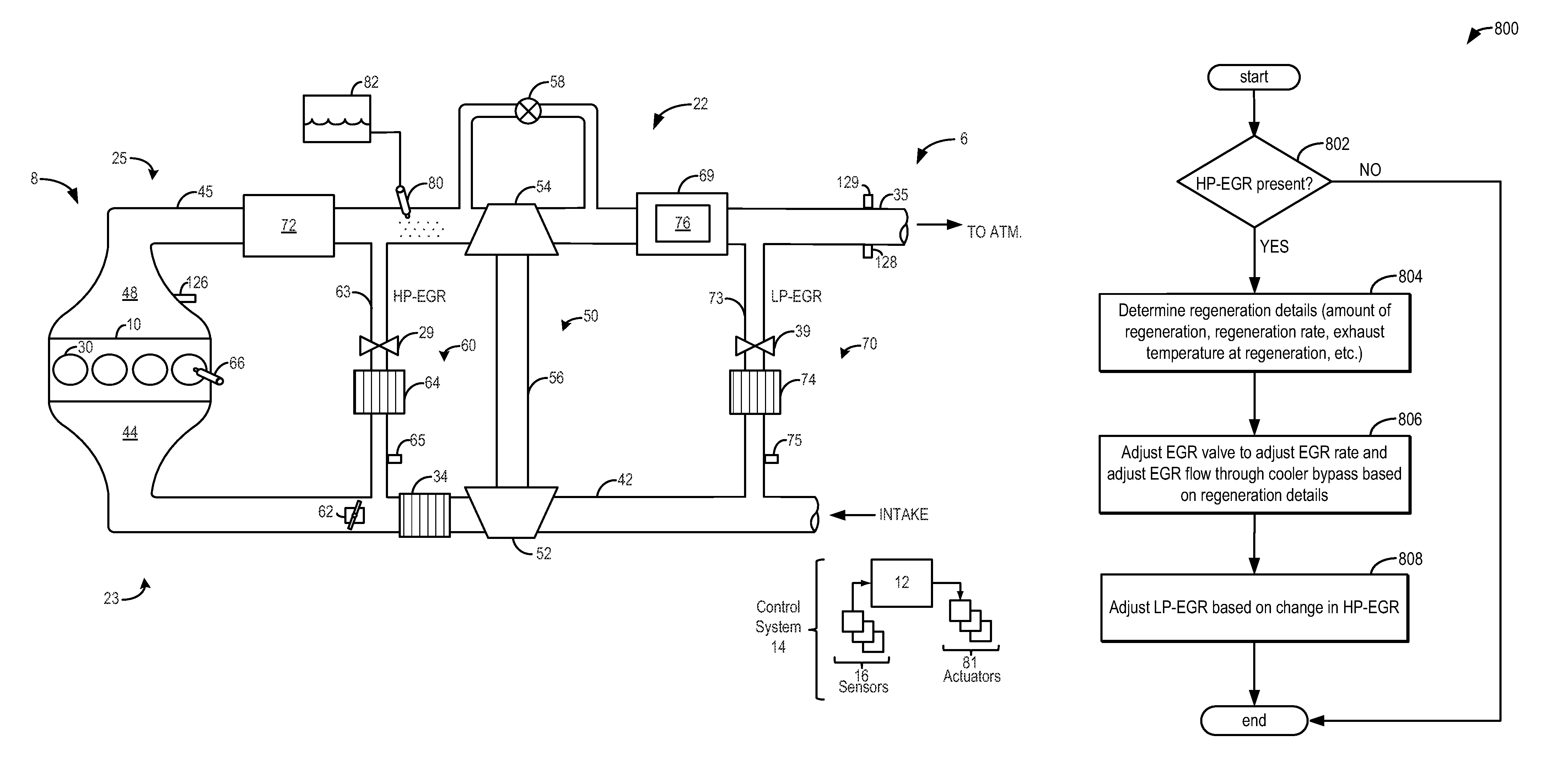
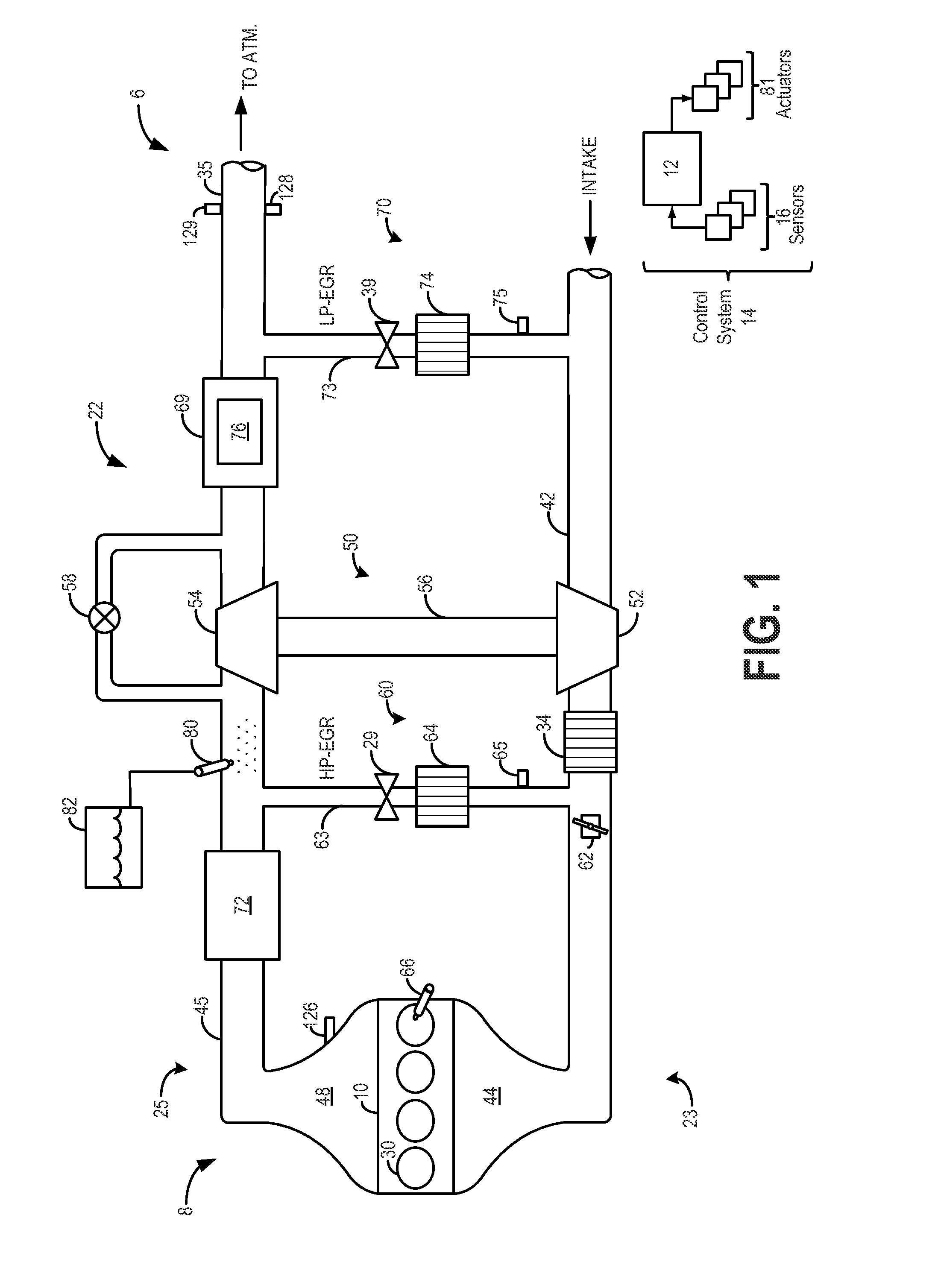
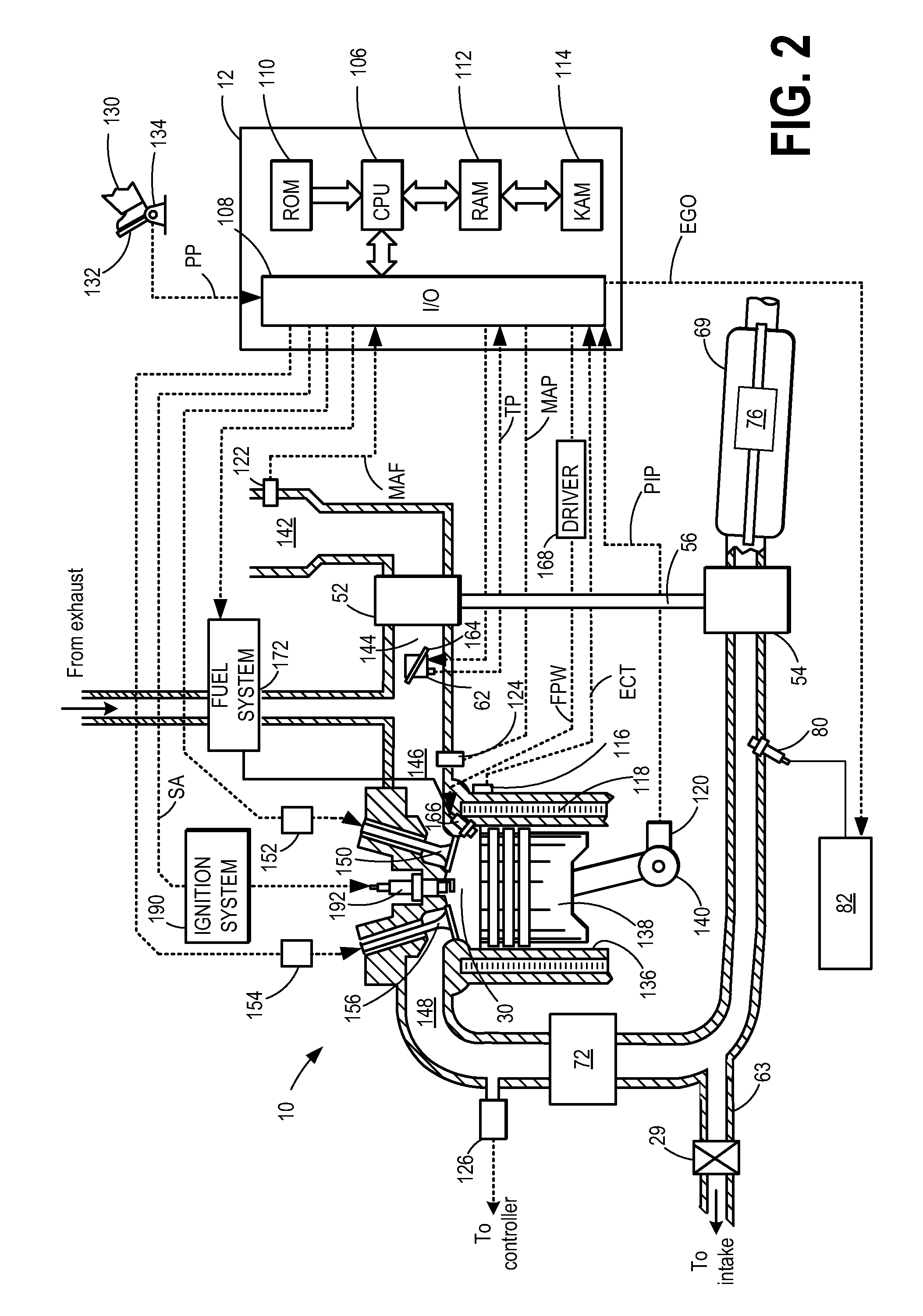
[0015]The following description relates to systems and methods for operating an emission control system associated with a turbocharged internal combustion engine. As shown in FIGS. 1-2, the emission control system includes a catalyst, such as an SCR catalyst, downstream of the turbocharger turbine, and a particulate filter, such as a diesel particulate filter (DPF), upstream of the turbine. A controller may be configured to perform a control routine, such as the routine of FIGS. 3A-B to coordinate the operation of the various emission control devices with each other, and with other engine operations such as exhaust gas recirculation and boosting.

[0016]The emission control system also includes a reductant injector upstream of the turbine. By injecting reductant upstream of the turbine and mixing the injected reductant with exhaust gas via the turbine, the vaporization of the reductant may be improved. At the same time, by positioning the catalyst downstream of the turbine, the well-m...


PUM


Abstract

Methods and systems are provided for operating a turbocharged engine including a particulate filter positioned upstream of a turbocharger turbine, a catalyst positioned downstream of the turbine, and an EGR passage coupled between an engine exhaust and engine intake. In one example, the method comprises, diverting exhaust gas from downstream of the filter to the engine intake via the EGR passage, and adjusting an amount of diverted exhaust gas based on filter operating conditions.

Description

FIELD[0001]The present application relates to methods and systems for emission control of a vehicle with a selective catalytic reduction (SCR) catalyst and a particulate filter.BACKGROUND AND SUMMARY[0002]Engine systems may use EGR (exhaust gas recirculation) to address exhaust NOx emissions. For example, EGR systems may divert exhaust gas from upstream of an exhaust turbine to downstream of an intake compressor, or from downstream of an exhaust turbine to upstream of an intake compressor. Various approaches may be used to control EGR systems and coordinate EGR operations with emission control operations. One example approach is illustrated by Arnold in US 2004 / 0050047 A1. Therein, a particulate filter is included in the EGR passage so that particulates may be removed from the EGR flow before exhaust gases are recirculated through the intake.[0003]However, the inventors herein have recognized several potential issues with such an approach. As one example, to regenerate the filter, h...

Claims


Application Information

Patent Timeline
Patent Type & Authority Patents(United States)
IPC IPC(8): F02B33/44F02B37/00F02M25/07F02M25/06F01N5/04F01N3/00
CPCF01N3/021F01N9/002F02D41/0007F02D41/0055F02D41/029F02M25/0707F02M25/0709F02M25/0718F01N2250/02F01N2570/10F02B29/0406F02D2200/0802F02M25/0727Y02T10/144Y02T10/20Y02T10/47F02M26/05F02M26/06F02M26/15F02M26/23Y02A50/20Y02T10/12Y02T10/40
Inventor HEPBURN, JEFFREY SCOTTRUONA, WILLIAM CHARLESFULTON, BRIEN LLOYDSURNILLA, GOPICHANDRAKURTZ, ERIC MATTHEW
Owner FORD GLOBAL TECH LLC
Why Eureka
Try Eureka