Ship with stern equipped with a device for deflecting a flow of water

a technology for stern and water flow, which is applied in the field of ships, can solve the problems of not necessarily optimal, high tonnage, and high efficiency of stern hull arrangement, and achieve the effect of not being applicable to ships with large dimensions and high tonnag

Active Publication Date: 2012-01-17
STX FRANCE CRUISE
View PDF10 Cites 26 Cited by
  • Summary
  • Abstract
  • Description
  • Claims
  • Application Information

AI Technical Summary

Benefits of technology

[0016]The object of the invention is therefore a ship with large dimensions and high tonnage, such as a cruise ship in particular, the stem of which is equipped with a device for deflecting flows of water, comprising several deflector members having a submerged lower face, called first face, fitting overall into the extension of the bottom of the hull, toward the rear thereof, while forming an angle in relation to a general plane tangent to this bottom, each of these deflector members being articulated to the hull, control means making it possible to cause it to pivot in one direction or the other in order to cause said angle to vary.
[0019]Moreover, the arrangement of the deflector members over all or nearly all of the width of the stem makes it possible to smooth the wave at the rear of the ship and to avoid the phenomenon of recirculation of the wave, which is a source of wasted energy.
[0022]said control means make it possible to vary said angle within a range comprised between a negative value, corresponding to an orientation of said first face inclined upward and rearward in relation to said general plane, and a positive value, corresponding to an orientation of this first face downward and rearward in relation to this general plane;
[0034]the stern of the ship is provided with a spoiler serving as shield able to protect the deflector member as well as the hydraulic jacks from the assault of the surge and waves coming from the rear.

Problems solved by technology

One drawback of the known deflectors is that their efficiency, in particular regarding power gains provided, depends on the trim of the ship (which can depend on its load and / or navigation conditions), as well as the ship's speed.
The dimensions and the angle of the “wedge” making up the deflector, which are determined in order to ensure maximum effectiveness under certain given trim and speed conditions, are therefore not necessarily optimal under other conditions.
This type of arrangement of the hull is not, however, applicable to a ship with large dimensions and high tonnage, which does not squat.
Moreover, it does not make it possible to avoid the recirculation of the wave at the rear of the ship, whereas this phenomenon is the source of a loss of propulsive energy for the ship (through increased friction and disruption of the flow in the vicinity of the blades of the propulsive means).
Moreover, this type of float body does not make it possible to resolve the problem of rear slamming, as the surge coming from the rear can freely penetrate under the rear counter, in the central zone of the boat which extends between the two float bodies.

Method used


Image

  • Ship with stern equipped with a device for deflecting a flow of water
  • Ship with stern equipped with a device for deflecting a flow of water
  • Ship with stern equipped with a device for deflecting a flow of water

Examples


Embodiment Construction

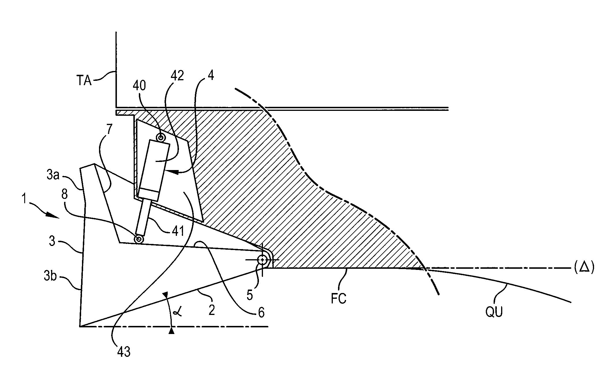
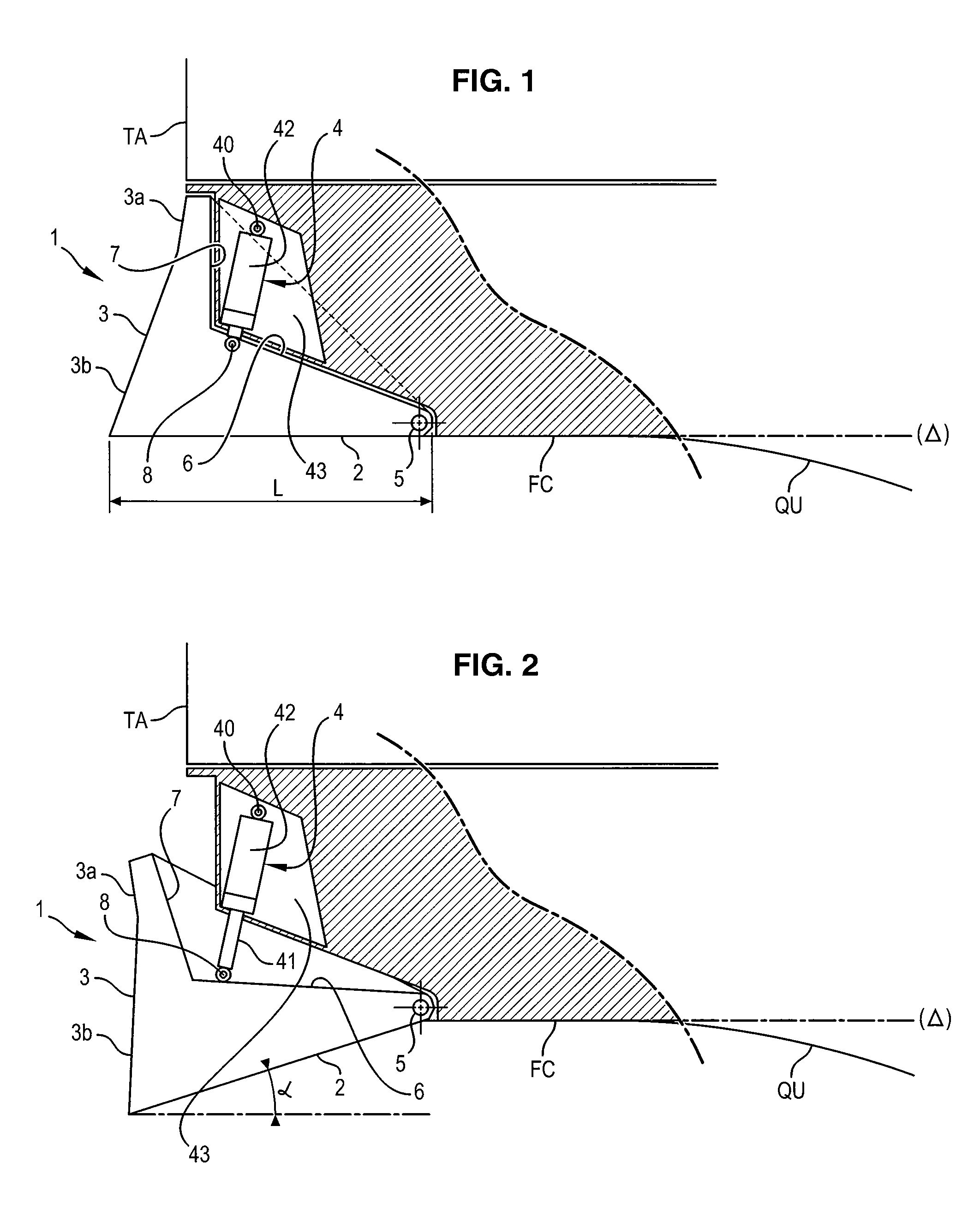
[0047]In reference to FIGS. 1 and 2, the reference 1 designates a deflector member arranged at the rear of a ship with large dimensions and high tonnage, such as a cruise ship, for example.

[0048]The reference FC designates the hull bottom, relatively flat, QU designates the rear portion of the keel, and TA designates the rear table of the stem.

[0049]The front of the ship is located on the right side of these figures.

[0050]The reference Δ corresponds to a plane in which the hull bottom FC fits overall at the level of the vertical cutting plane corresponding to FIGS. 1 and 2.

[0051]The deflector member 1 essentially comprises two walls in the form of functional faces 2 and 3.

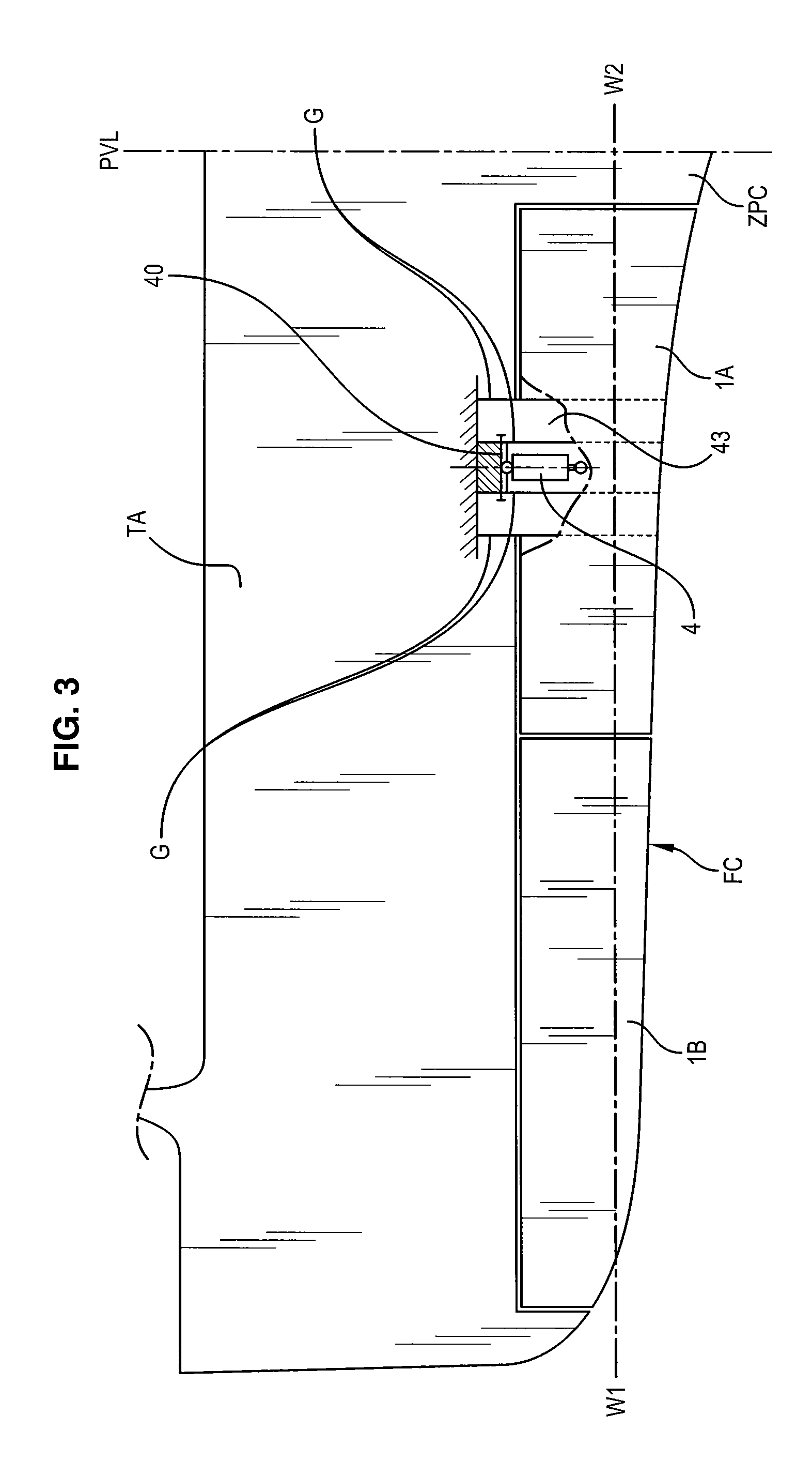
[0052]The first face 2 is approximately flat (except for its slight transverse curve, visible in FIG. 3), and turned downward.

[0053]Purely for information, its longitudinal dimension, referenced L in FIG. 1, is between approximately 4 and 5 meters.

[0054]The second face 3 is turned toward the rear. It is made up of ...


PUM


Abstract

The device comprises a plurality of deflector members (1) having a submerged lower face (2), called first face, generally fitting into the extension of the hull bottom (FC) of the ship, toward the rear thereof, while forming an angle (α) in relation to a general plane (Δ) tangent to this bottom (FC), characterized by the fact that these deflector members (1) are articulated to the hull and are juxtaposed side by side, over all, or practically all, the width of the stern, control means (4) making it possible to cause it to pivot in one direction or the other in order to vary said angle (α), these means being housed in part in a protective case.

Description

BACKGROUND OF THE INVENTION[0001]1. Field of the Invention[0002]The present invention concerns a ship whereof the stern is equipped with a device for deflecting a flow of water.[0003]It more particularly concerns a ship with large dimensions and a high tonnage, such as a cruise ship in particular, the displacement speed of which is relatively limited in relation to that of light and fast boats, this speed being between 10 and 25 knots or approximately between 18 and 45 km / h in cruising speed, for information, and the Froude number of which does not exceed 0.28.[0004]2. Discussion of Related Art[0005]It is known to equip the hull of a ship of this type with a deflector member in wedge form, positioned below the waterline, in the connection zone of the bottom of the hull with the rear flank—or bow—of the ship.[0006]The function of a deflector of this type, generally designated by the expression “trim wedge”, is to deviate, downward and rearward, the flow of water in relative movement,...

Claims


Application Information

Patent Timeline
Patent Type & Authority Patents(United States)
IPC IPC(8): B63B1/22
CPCB63B39/061B63B1/28
Inventor MORAND, LOICCHARDIN, GERVAISCOLLIN, JEAN-PIERRE
Owner STX FRANCE CRUISE
Why Eureka
Try Eureka