Hydraulic machine and application method thereof

A technology of hydraulic press and body, applied in the field of presses, can solve the problem that the pressure cannot be further increased, and achieve the effect of increasing pressure, increasing tonnage, and increasing tonnage

Inactive Publication Date: 2015-12-30
安徽省华夏机床制造有限公司
View PDF8 Cites 2 Cited by
  • Summary
  • Abstract
  • Description
  • Claims
  • Application Information

AI Technical Summary

Problems solved by technology

[0007] Aiming at the problem that the existing hydraulic machine is limited by the volume of the oil cylinder and the pressure cannot be further increased, the present invention provides a hydraulic machine and its use method, which can break through the bottleneck of the tonnage of the traditional hydraulic machine limited by the volume of the oil cylinder, and further increase the pressure of the hydraulic machine without increasing the production cost , compared with the hydraulic press of the same tonnage, the use is more flexible and the production efficiency is improved

Method used


Image

  • Hydraulic machine and application method thereof
  • Hydraulic machine and application method thereof
  • Hydraulic machine and application method thereof

Examples


Embodiment 1

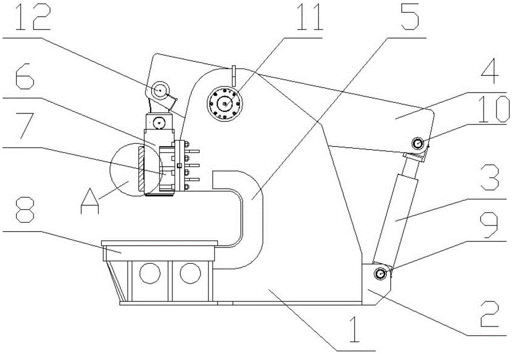
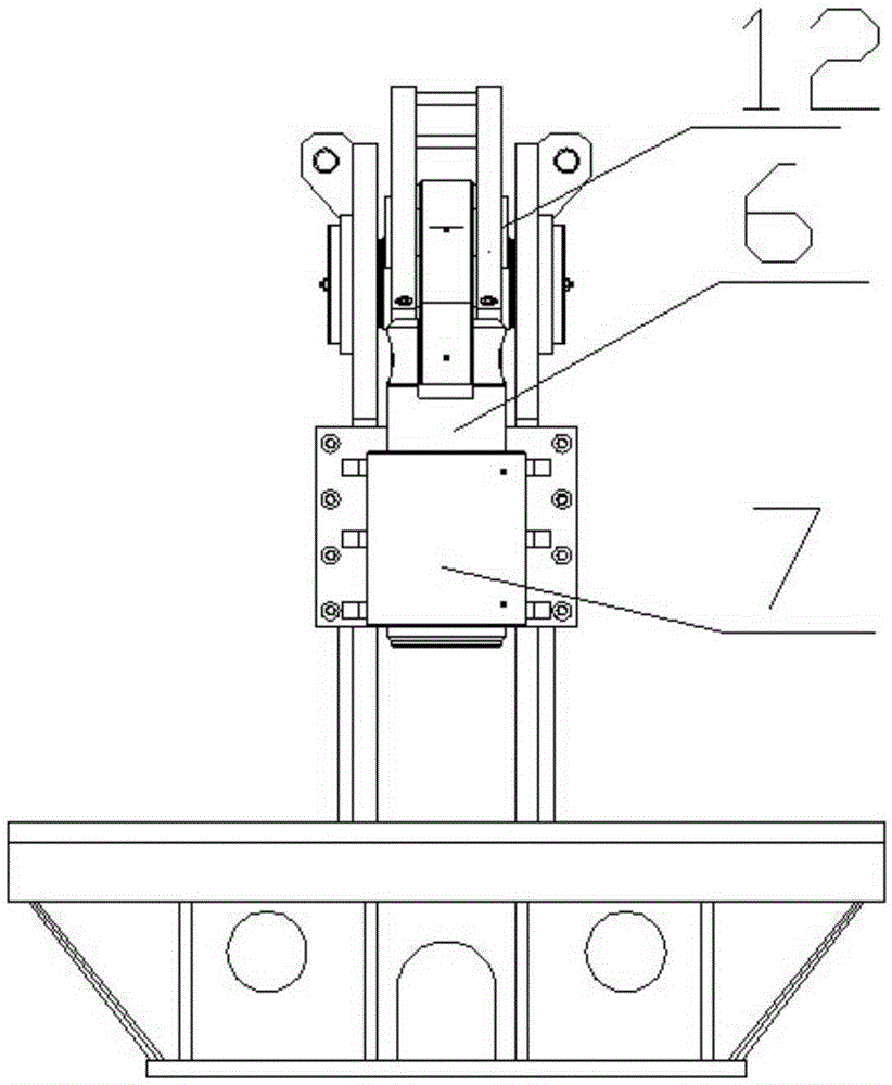
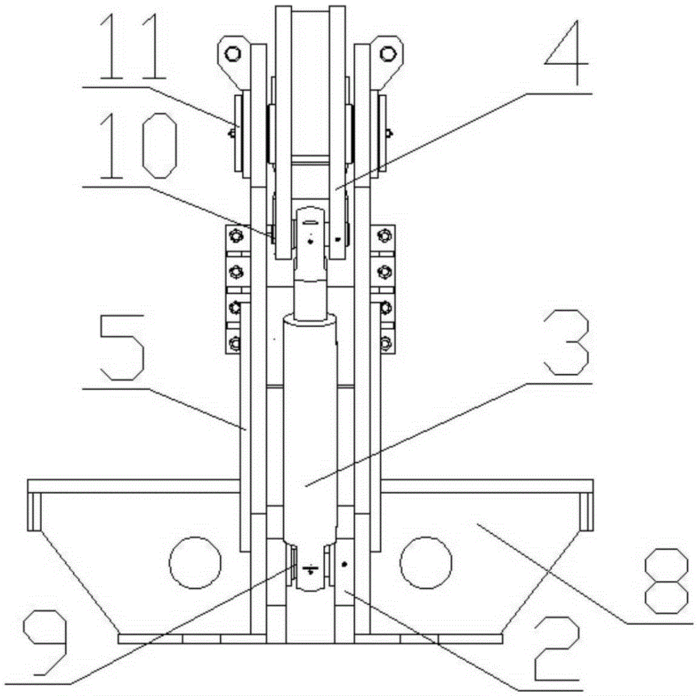
[0054] Such as Figure 1-8 As shown, a hydraulic machine includes a body 1, an oil cylinder 3, a slider 6 and a workbench 8. The body 1 is in the shape of a "C" and has a "C"-shaped opening; the workbench 8 is set on the "C"-shaped opening of the body 1. The lower side of the direction also includes a beam arm 4, a first pin shaft 9, a second pin shaft 10, a third pin shaft 11, a fourth pin shaft 12 and a guide slide 7; the beam arm 4 is arranged on the top of the body 1, and the beam arm 4. Pass the third pin shaft 11 through the third pin shaft hole 402 provided in the middle of the beam arm 4 and the pin shaft hole on the top of the body 1 to connect with the body 1;

[0055] The two ends of the beam arm 4 are respectively provided with a second pin hole 401 and a fourth pin hole 403; the second pin hole 401, the third pin hole 402, and the fourth pin hole 403 in the beam arm 4 are on the same section The centers of circles are on the same straight line, and on the same se...

Embodiment 2

[0067] Same as Example 1, the difference is: L 1 with L 2 The relationship between them is: L 1 =2.5L 2 ; The angle between the bottom surface 405 of the front end of the beam arm and the bottom surface 407 of the rear end of the beam arm is 150°.

[0068] The using method of the hydraulic press in the present embodiment is the same as the using method in the embodiment 1, the difference is: the oil cylinder 3 piston rod stretches out in the step 4), pushes the beam arm 4 one end along the radius L 1 The first circular arc trajectory moves upward, the beam arm 4 rotates around the first pin shaft 9, and the end of the beam arm 4 close to the worktable 8 along the radius L 2 =2 / 5L 1The circular arc track moves downward, and pushes the slider 6 to move. One end of the slider connecting plate 601 on the slider 6 rotates around the fourth pin 12, and the other end rotates around the pin connected to the slider connecting end 602. The slider The rotary motion at the two ends o...

Embodiment 3

[0070] Same as Example 1, the difference is: L 1 with L 2 The relationship between them is: L 1 =3.5L 2 ; The angle between the bottom surface 405 at the front end of the beam arm and the bottom surface 407 at the rear end of the beam arm is 160°.

[0071] The using method of the hydraulic press in the present embodiment is the same as the using method in the embodiment 1, the difference is: the oil cylinder 3 piston rod stretches out in the step 4), pushes the beam arm 4 one end along the radius L 1 The first circular arc trajectory moves upward, the beam arm 4 rotates around the first pin shaft 9, and the end of the beam arm 4 close to the worktable 8 along the radius L 2 =2 / 7L 1 The circular arc track moves downward, and pushes the slider 6 to move. One end of the slider connecting plate 601 on the slider 6 rotates around the fourth pin 12, and the other end rotates around the pin connected to the slider connecting end 602. The slider The rotary motion at the two ends ...


PUM


Abstract

The invention discloses a hydraulic machine and an application method thereof, belongs to the field of pressing machines, and aims to solve the problem of the pressure of a conventional hydraulic machine cannot be further improved due to the limit of oil cylinder volume. The hydraulic machine comprises a machine body, an oil cylinder, a sliding block and a worktable; the worktable is arranged on the lower side of the 'C'-shaped opening direction of the machine body; the hydraulic machine further comprises a beam arm and a guiding slideway; the beam arm is arranged at the top of the machine body; a second pin shaft hole and a fourth pin shaft hole are respectively formed in the two ends of the beam arm; an oil cylinder seat is arranged on the lower side at the opposite end of the 'C'-shaped opening direction of the machine body; one end of the oil cylinder is connected onto the oil cylinder seat through a first pin shaft, and the other end of the oil cylinder is connected onto the second pin shaft hole through a second pin shaft; one end of the sliding block is connected onto the fourth pin shaft hole through a fourth pin shaft, and the other end of the sliding block penetrates through the guiding slideway and faces and is perpendicular to the worktable. The bottleneck that the tonnage of the conventional hydraulic machine is limited by the oil cylinder volume is broken through, the pressure of the hydraulic machine is further increased, meanwhile, the production cost is not increased, the use is relatively flexible, and the production efficiency is improved.

Description

technical field [0001] The invention belongs to the field of presses, and in particular relates to a hydraulic press and a method for using the same. Background technique [0002] A hydraulic press is a machine that uses liquid as a working medium and is made according to Pascal's principle to transfer energy to realize various processes. The hydraulic press is generally composed of three parts: the main engine, the power system and the hydraulic control system. Hydraulic presses are classified into valve hydraulic presses, liquid hydraulic presses, and engineering hydraulic presses. A hydraulic press uses hydrostatic pressure to process metal, plastic, rubber, wood, powder and other products. It is often used in pressing process and pressing forming process, such as: forging, stamping, cold extrusion, straightening, bending, flanging, sheet drawing, powder metallurgy, pressing and so on. Hydraulic presses are classified according to the type of liquid that transmits pres...

Claims


Application Information

Patent Timeline
Patent Type & Authority Applications(China)
IPC IPC(8): B30B1/32B30B15/04
Inventor 费文彪
Owner 安徽省华夏机床制造有限公司
Why Eureka
Try Eureka