Turbine blade assembly

a technology of turbine blades and components, applied in the direction of liquid fuel engines, marine propulsion, vessels, etc., can solve the problems of not being able to fit traditional plates, and achieve the effects of reducing the cost of machined alternatives, preventing excessive leakage, and preventing excessive leakag

Inactive Publication Date: 2012-01-17
SIEMENS AG
View PDF19 Cites 15 Cited by
  • Summary
  • Abstract
  • Description
  • Claims
  • Application Information

AI Technical Summary

Benefits of technology

[0013]The locking plates retain the blades during engine operation which is necessary for security. The locking plates also provide sealing of cooling air to prevent excessive leakages. The castellated edges of the locking plates allow for insertion into the castellated insertion part of the rim of the circular groove of the turbine disc even after all turbine blades are mounted to the disc. The gaps of the insertion part and the teeth of the locking plates correspond to allow for insertion of the locking plates into the grooves.
[0014]In an advantageous development of the invention the locking plates are sprung. This retains the blades during engine operation. In addition, the spring-back will provide the required force to seal against the disc rear face and prevent leakages of the high pressure cooling air to cool the internals of the high pressure turbine blades.
[0015]Another advantage is the sprung locking plates can be easily formed from sheet metal giving a significant cost reduction to machined alternatives.
[0017]The locking plates may also comprise a flat portion outside the at least one bent portion which allows for flat rest against the turbine disc and therefore provides good sealing.

Problems solved by technology

However, where blades are assembled into discs as a full engine set (e.g. where root and platform angles are different) it is not possible to fit traditional plates as the retaining grooves in the disc and blade are full rings—therefore a new method is required.

Method used


Image

  • Turbine blade assembly
  • Turbine blade assembly
  • Turbine blade assembly

Examples


Embodiment Construction

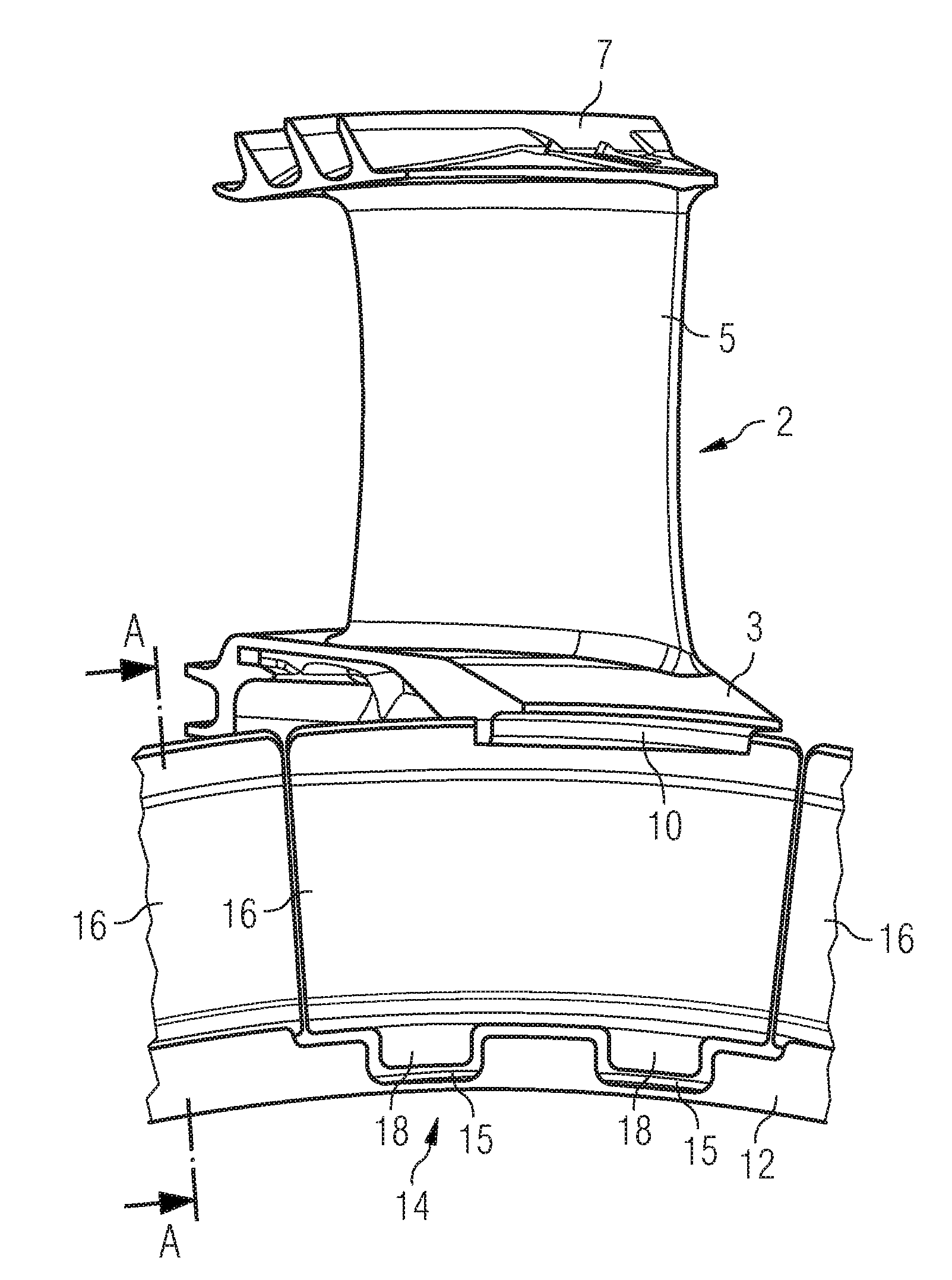
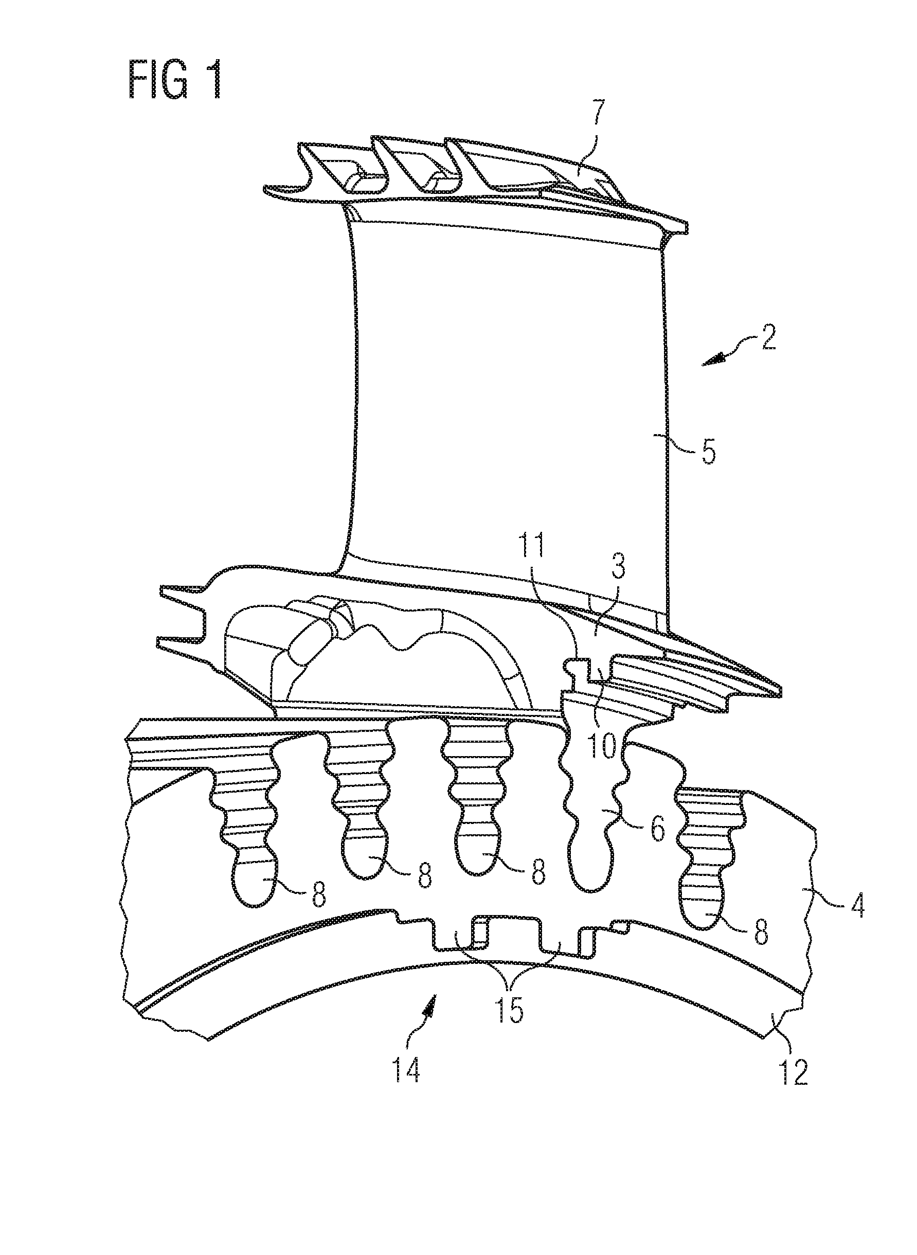
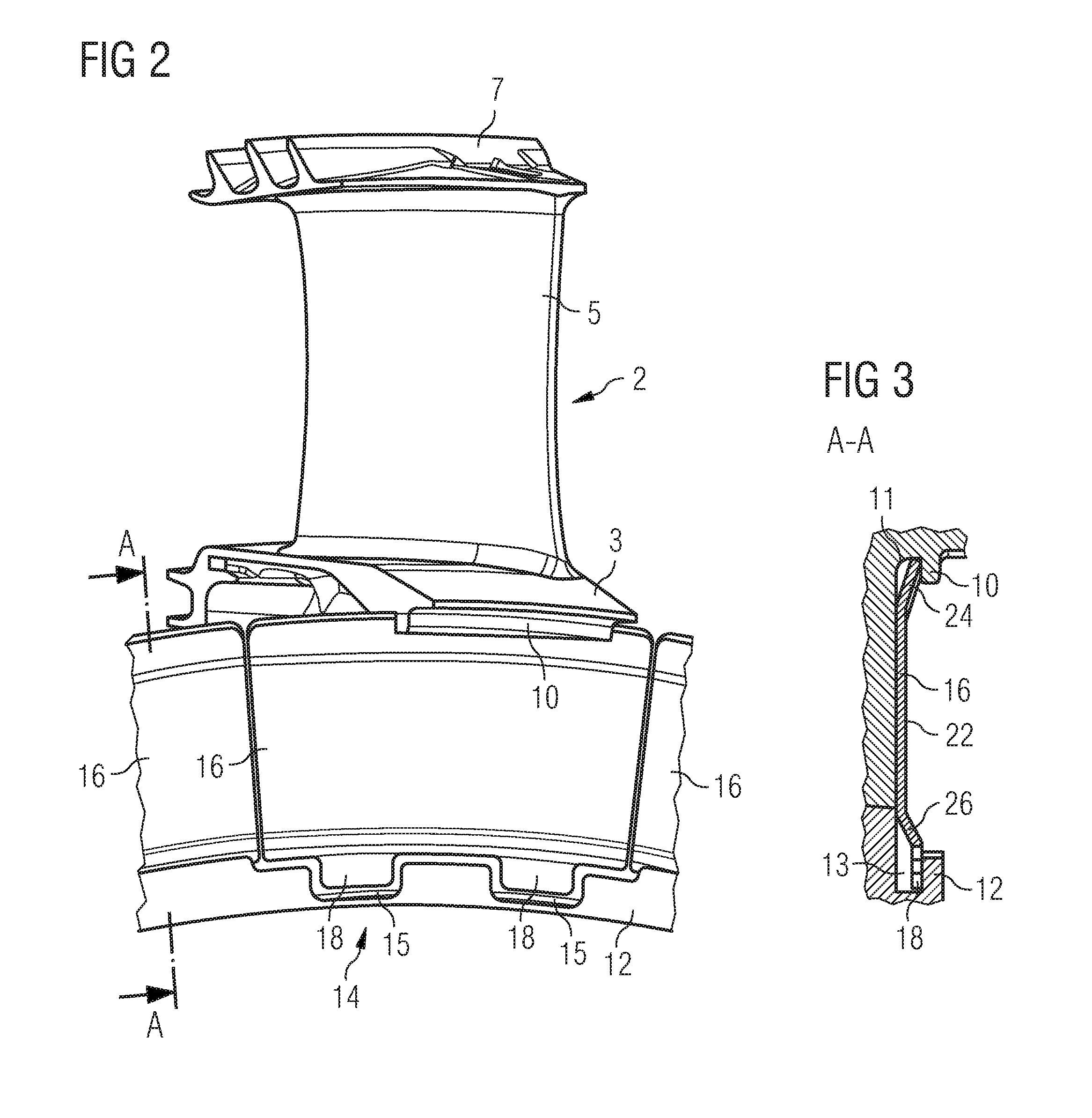
[0024]FIG. 1 shows a turbine blade assembly with a turbine blade 2, comprising a top portion 7, an airfoil 5, a platform 3, a groove 11 with a rim 10 and a turbine blade root 6 and a turbine disc 4 comprising notches 8 and a circular groove 13 (see FIG. 3) with a rim 12 comprising a castellated part 14 with gaps 15.

[0025]The turbine blade 2 is used in a gas turbine where hot pressurized gas is guided towards turbine blades with airfoils that are fixed on a rotor to move the turbine blades and thus drive the rotor. The rotor comprises several turbine discs 4. The turbine blades 2 are mounted to a turbine disc 4 by their turbine blade roots 6 that are inserted into notches 8 of the turbine disc 4. Although the notches 8 in FIG. 1 are oriented axially through the disc 4 so that they extend more or less perpendicular to the end and back faces of the disc 4 they may sometimes be oriented such that they extend more or less tangential to the end and back faces of the disc.

[0026]The platfor...


PUM


Abstract

A turbine blade assembly, in particular of a gas turbine, is provided. The turbine blade assembly includes a turbine disc with rotor blades inserted into notches of the turbine disc and locking plates that are placed inside circular grooves with rims in the turbine disc and in the rotor blade. The edges of the locking plates that are oriented towards the center of the turbine disc are castellated by providing teeth and accordingly a part of the rim of the circular groove of the turbine disc is also castellated by providing gaps and whereby the gaps of the rim match the teeth of the locking plates. The locking plates have a spring-back force to provide both locking and sealing capabilities during engine operation.

Description

CROSS REFERENCE TO RELATED APPLICATIONS[0001]This application is the US National Stage of International Application No. PCT / EP2007 / 059086, filed Aug. 31, 2007 and claims the benefit thereof. The International Application claims the benefits of European Patent Office application No. 06022426.8 EP filed Oct. 26, 2006, both of the applications are incorporated by reference herein in their entirety.BACKGROUND OF THE INVENTION[0002]The invention relates to turbine blade assemblies, in particular for gas turbines.[0003]Blade locking in turbine discs must be performed to ensure blades do not become loose during engine operation. For high pressure turbine blades, locking plates have traditionally been employed to provide both security and sealing of cooling air to prevent excessive leakages, these plates being assembled using a sequential build technique. However, where blades are assembled into discs as a full engine set (e.g. where root and platform angles are different) it is not possibl...

Claims


Application Information

Patent Timeline
Patent Type & Authority Patents(United States)
IPC IPC(8): B63H1/20B63H13/00
CPCF01D5/3015F05D2250/182F05D2250/70F05D2260/30
Inventor BLUCK, RICHARDCHARLTON, SCOTT
Owner SIEMENS AG
Why Eureka
Try Eureka