Method and arrangement in wind power plant

a technology of wind power plants and wind power generators, applied in the direction of electric generator control, machines/engines, mechanical equipment, etc., can solve the problems of inability to achieve the effect of increasing the efficiency of wind power plants, and reducing the loss of wind power plants

Active Publication Date: 2012-01-17
ABB (SCHWEIZ) AG
View PDF56 Cites 24 Cited by
  • Summary
  • Abstract
  • Description
  • Claims
  • Application Information

AI Technical Summary

Benefits of technology

[0008]The disclosure is based on the idea that some of the mains converter parts of a modular frequency converter may be formed of smaller components than those employed in a conventional modular structure. This structure enables frequency converter operation such that at low powers produced by the generator it is possible to select a mains converter part whose rating may be selected more accurately than previously to correspond to the transmitted power.
[0009]The modular structure of the disclosure also enables smaller dimensions of the mains converter, which is of particular importance in connection with wind power drives, as they are located in structures that are complicated to implement. In addition, the method and the arrangement of the disclosure enable improvement in efficiency of the wind power plant, because a more optimally selected mains converter produces smaller losses.

Problems solved by technology

Implementation of one converter having sufficiently high power is often technically extremely complicated, because voltage and current capacities of the required power semiconductors set limits to powers to be used.
A disadvantage with the known solution is that power steps in the mains converter are wide, and consequently at low transmitted powers, in particular, an undesirable amount of current harmonics is transferred to the network.

Method used


Image

  • Method and arrangement in wind power plant
  • Method and arrangement in wind power plant
  • Method and arrangement in wind power plant

Examples


Embodiment Construction

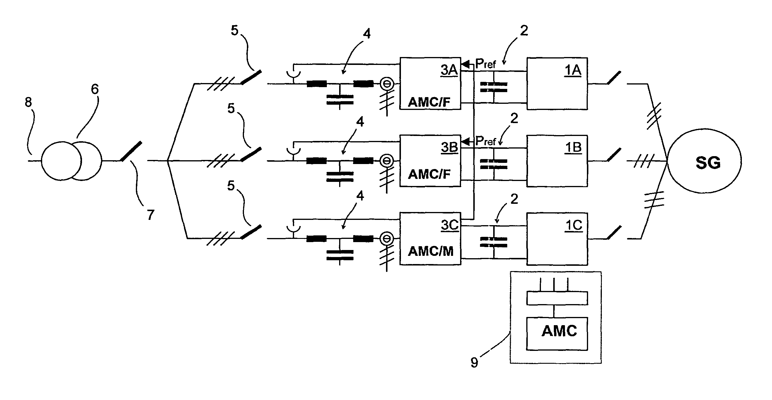
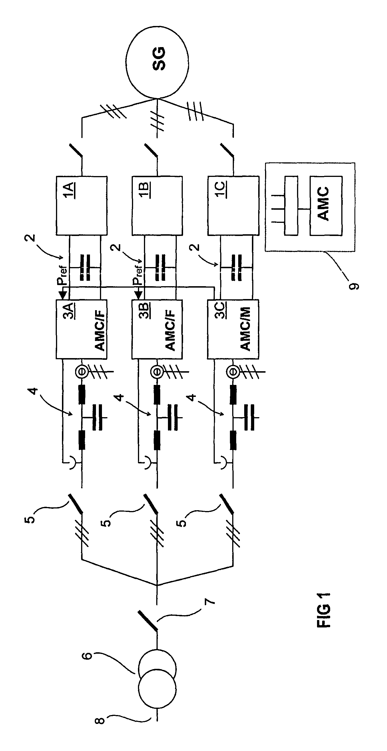
[0014]FIG. 1 is a graph showing the principle of an arrangement in accordance with the disclosure including three partial converters in parallel. Each partial converter comprises an inverter part 1A, 1B, 1C and a mains converter part 3A, 3B, 3C, as well as a DC voltage intermediate circuit 2 between them. Further, the electric drive of a wind power plant as shown in FIG. 1 includes a generator SG with a winding connected to each parallel partial converter, and consequently each partial converter together with the generator constitutes an independent whole. Voltage is induced in each parallel winding of the generator, the magnitudes thereof corresponding one another. Typically, these windings are formed such that they are not electrically interconnected. However, it is obvious that the operation of the inventive method does not depend on the generator type.

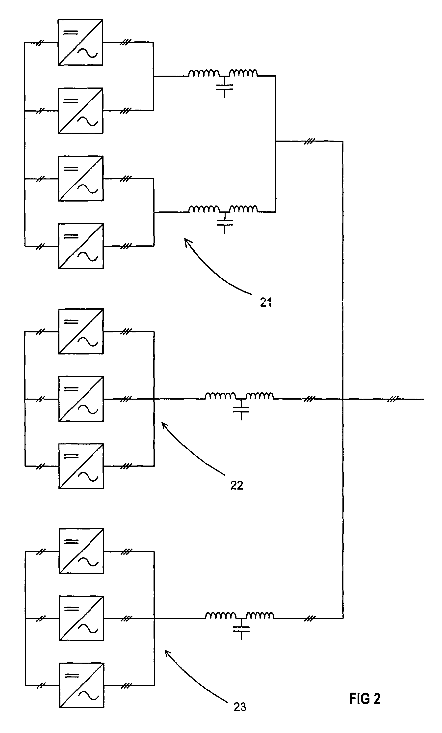
[0015]Each partial converter also includes a mains filter 4, which is shown in FIG. 1 as a three-phase filter of LCL type. The fu...


PUM


Abstract

A method and an arrangement in connection with a wind power plant, an electric drive of the wind power plant comprising two or more partial converters in parallel, which constitute a frequency converter of the electric drive, and each partial converter comprising a mains converter part, of which the nominal power of at least one differs from the nominal power of other mains converter parts, and in the method there is selected for use the smallest possible, individual mains converter part required by an operating point of the wind power plant, or a combination of mains converter parts.

Description

RELATED APPLICATIONS[0001]This application claims priority under 35 U.S.C. §119 to Finnish Patent Application No. 20065700 filed in Finland on Nov. 6, 2006, the entire contents of which are hereby incorporated by reference in their entireties.TECHNICAL FIELD[0002]A method and an arrangement is disclosed in connection with a wind power plant, and in particular to optimization of wind power plants as regards effects on the network.BACKGROUND INFORMATION[0003]As the structures of wind power plants increase in size, it is often necessary to implement electric drives of the wind power plants in a modular manner. This is the case, for instance, in connection with wind power plants, in which a wind turbine is allowed to rotate at a variable speed depending on wind conditions. A generator run by the wind turbine produces electric energy that is supplied to the grid. As the speed of the wind turbine varies, the frequency of the electric energy produced by the generator also varies. Hence, at...

Claims


Application Information

Patent Timeline
Patent Type & Authority Patents(United States)
IPC IPC(8): F03D9/00H02P9/04
CPCF03D7/0272H02P9/42H02J3/386F05B2270/1041F05B2270/504H02P2101/15Y02E10/763H02M2007/4822Y02E10/723H02M7/493H02J2300/28H02J3/381Y02E10/72Y02E10/76H02J3/38H02M5/4585
Inventor HYVARINEN, VEIKKO
Owner ABB (SCHWEIZ) AG
Why Eureka
Try Eureka