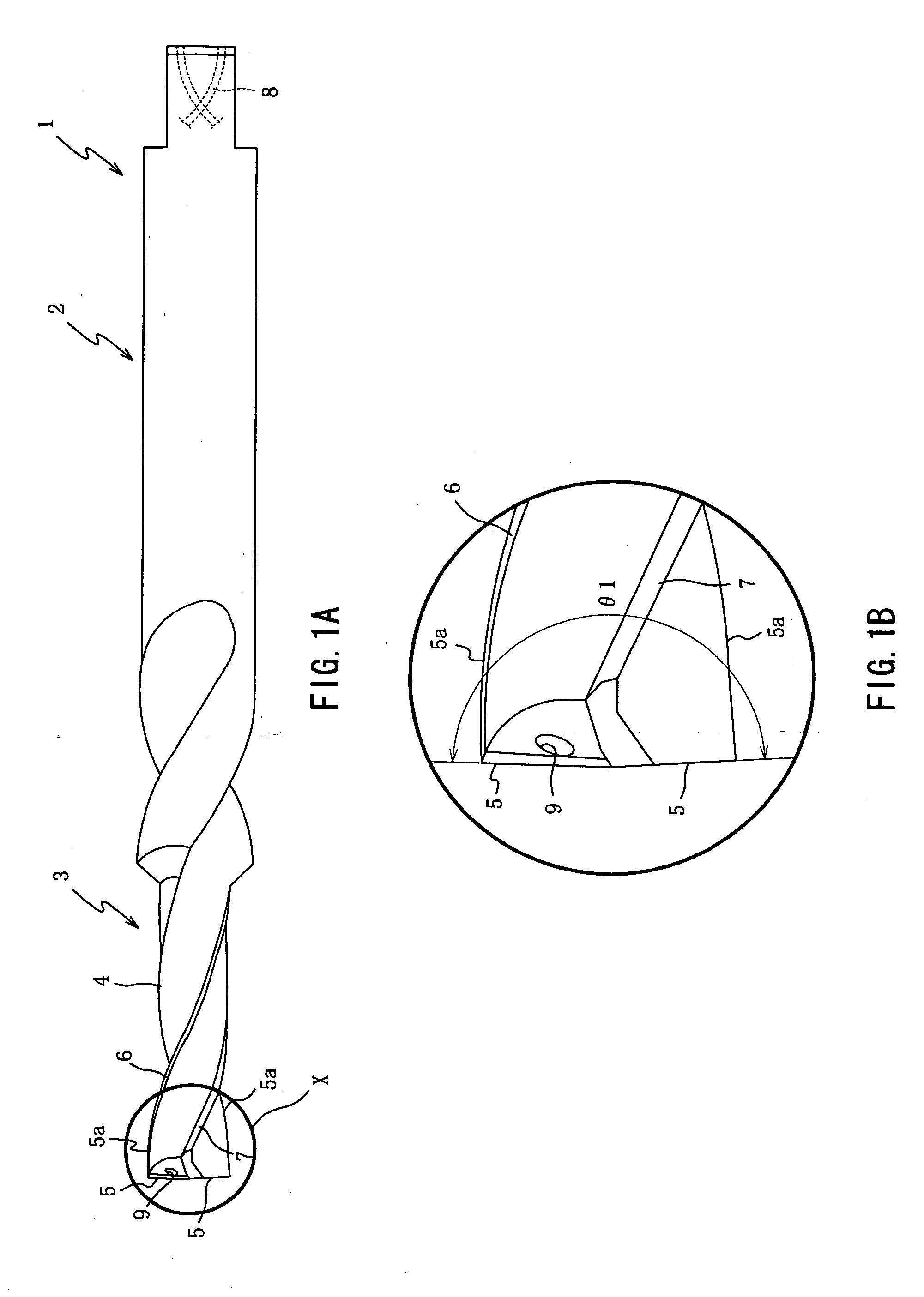
[0018] The drill according to the present invention in which the point angle is not smaller than about 170° and is smaller than about 180°, is capable of
machining or enlarging a hole previously formed in a workpiece, with a smaller radial component of a cutting resistance or force acting on the drill, than a conventional drill in which the point angle is not smaller than 120° and is not larger than 140°. Therefore, even if the axis of the cylindrical main body of the drill is not aligned with an axis of the previously formed hole while the hole is being enlarged by the drill, it is possible to minimize run out or deflection of the drill, namely, restrain the axially distal end portion of the cylindrical main body of the drill from becoming eccentric with respect to an axis of a spindle of a
machine tool used for the drilling operation, thereby restraining deviation of the point of the drill from a target position, and resulting in a high positional accuracy of the enlarged hole. Further, the reduction in the radial component of the cutting resistance leads also to a reduction in chattering of the drill, thereby making it possible to prolong the tool life of the drill.
[0019] Further, in the drill according to the invention, each of the cutting edges is substantially straight as seen in the direction perpendicular to the axis, or is curved such that each of the cutting edges is convexed as seen in the direction perpendicular to the axis. Either one of these arrangements is effective to cause the radial component of the cutting force to act on the drill inwardly in the radial direction rather than outwardly in the radial direction, thereby avoiding outward displacement of the point of the drill from in the radial direction and accordingly preventing deterioration in the positional accuracy of the enlarged hole. This is contrast to an arrangement in which each cutting edge is curved to be concaved as seen in the direction perpendicular to the axis. This concaved arrangement causes the radial component of the cutting force to act on the drill in a direction away from the axis, i.e., in the radially outward direction, whereby the point of the drill tends to be displaced outwardly in the radial direction.
[0020] While each cutting edge may be either straight or curved to be convexed, the convexed cutting edge arrangement is advantageous over the straight cutting edge arrangement, in positional accuracy of the machined hole and in cutting efficiency. That is, in the convexed cutting edge arrangement, the radial component of the cutting force can be made still smaller than in the straight cutting edge arrangement, so that the run out of the drill can be made still smaller than in the straight cutting edge arrangement, whereby the positional accuracy of the machined hole can be further improved. Further, in the convexed cutting edge arrangement, each cutting edge can be brought into contact with a larger surface area of the workpiece than in the straight cutting edge arrangement, whereby the cutting efficiency is further increased.
[0021] The drill defined in the third aspect of the invention is given excellent cutting capacity and enhanced
wear resistance, owing to the formation of its cylindrical main body with the
cemented carbide. The excellent cutting capacity and enhanced
wear resistance lead to further improvements in the cutting efficiency and accuracy, and also to further
prolongation of its tool life. It is therefore preferable that the cylindrical main body of the drill is formed of the
cemented carbide. However, it may be formed of other material such as
high speed steel.
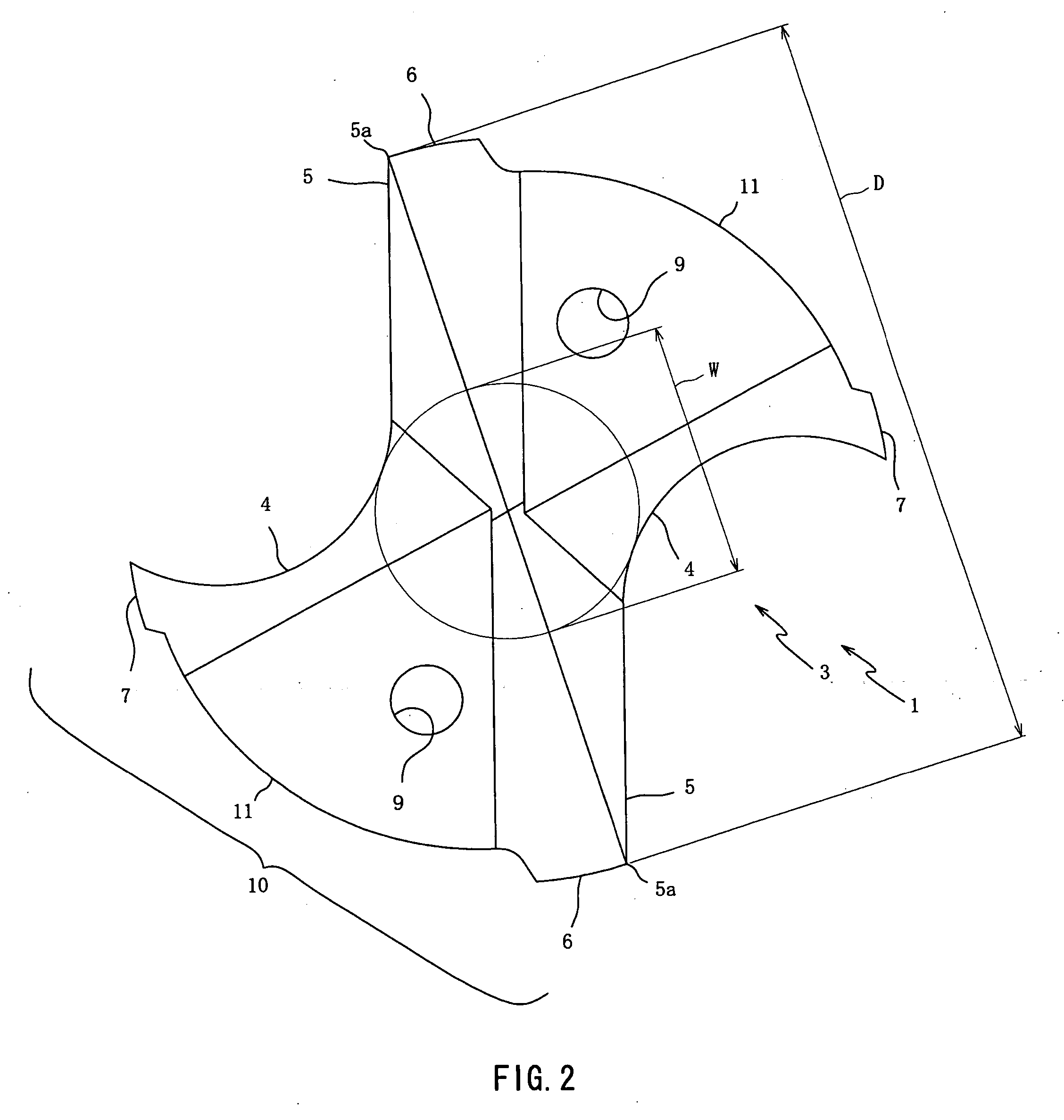
[0022] In the drill defined in the fourth aspect of the invention, each of the lands has, in addition to the first margin provided by its front-side end portion, the second margin provided by its rear-side end portion. In a drilling operation with this drill, the hole is drilled by the cutting edges, and at the same time the drilled hole is ground or burnished by the first and second margins. It should be noted that the provision of the two margins in each land provides a higher degree of smoothness of the machined hole than where only a single margin provided in each land. Since the hole machined by this drill is thus given the high degree of
surface smoothness, the drilled hole does not need to be finished by a
reamer or any other finishing tool which is to be used exclusively for finishing an inner circumferential surface of the machined hole. The
elimination of necessity of a finishing step by the finishing tool leads to reduction in number of steps in a process of manufacturing a product, and the consequent reduction in a cost required for manufacturing the product.
[0023] The drill constructed according to the invention can be advantageously used for the process, as defined in the above-described tenth aspect of the invention, of enlarging the hole which is previously formed in the workpiece in a die-
casting processing. Owing to the above-described technical advantages provided by the drill, the drill does not have to be accurately positioned relative to the workpiece in such a position that permits the axis of the cylindrical main body of the drill to be precisely aligned with the axis of the previously formed hole, prior to the feed of at least one of the drill and the workpiece toward the other in the axial direction. That is, even without the precise alignment of the axes which generally requires a cumbersome operation, the hole can be enlarged with a high positional accuracy thereof. Thus, the drill according to the present invention is useful in enlarging a hole preformed in a workpiece, particularly, in a die-casting process. However, it is advantageous over conventional drills, not only where the hole that is to be enlarged is preformed in a die-casting process but also where it is machined or otherwise formed, as long as there is a possibility that the preformed hole is intended to be enlarged by the drill without aligning the axis of the drill with an axis of the preformed hole.


