Driving circuit of light emitting diode and lighting apparatus

a technology of light-emitting diodes and driving circuits, which is applied in the direction of drug compositions, process and machine control, instruments, etc., can solve the problems of increasing the complexity of peripheral circuits and increasing the cost of fabrication

Inactive Publication Date: 2012-01-17
CAL COMP ELECTRONICS
View PDF3 Cites 38 Cited by
  • Summary
  • Abstract
  • Description
  • Claims
  • Application Information

AI Technical Summary

Benefits of technology

[0009]The present invention is directed to a lighting apparatus, which can receive an AC power from a dimmer to provide a stable driving voltage and driving current, so that a LED can provide a corresponding stable brightness according to the driving voltage and the driving current.
[0021]Accordingly, the lighting apparatus of the present invention includes the driving circuit of the LED and the LED, so that the lighting apparatus having the LED can be directly installed on a conventional lamp base, and a light brightness thereof can be adjusted by a conventional dimmer. The driving circuit can receive the AC power provided by the dimmer, and can continuously provide a stable driving voltage and driving current according to a duty cycle of a pulse signal and the PWM signal through bypass components of the resistors, the diode and the capacitors. Accordingly, not only the brightness of the LED of the light apparatus can be adjusted, but also a flickering phenomenon of the LED generated due to waveform variation of the AC power can be avoided.

Problems solved by technology

However, a complexity of peripheral circuits can be increased according to the above technique, and a fabrication cost can be increased due to a high price of a driver IC.

Method used


Image

  • Driving circuit of light emitting diode and lighting apparatus
  • Driving circuit of light emitting diode and lighting apparatus
  • Driving circuit of light emitting diode and lighting apparatus

Examples


Embodiment Construction

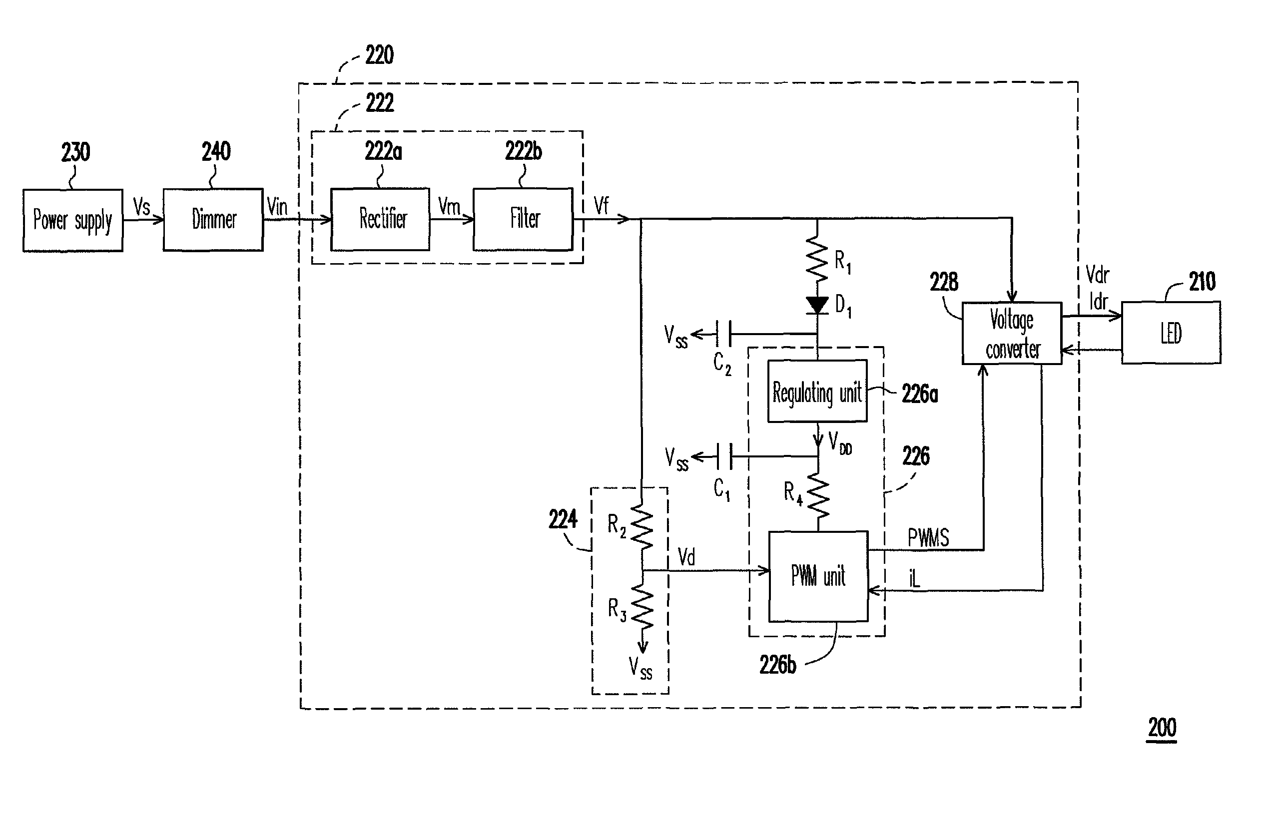
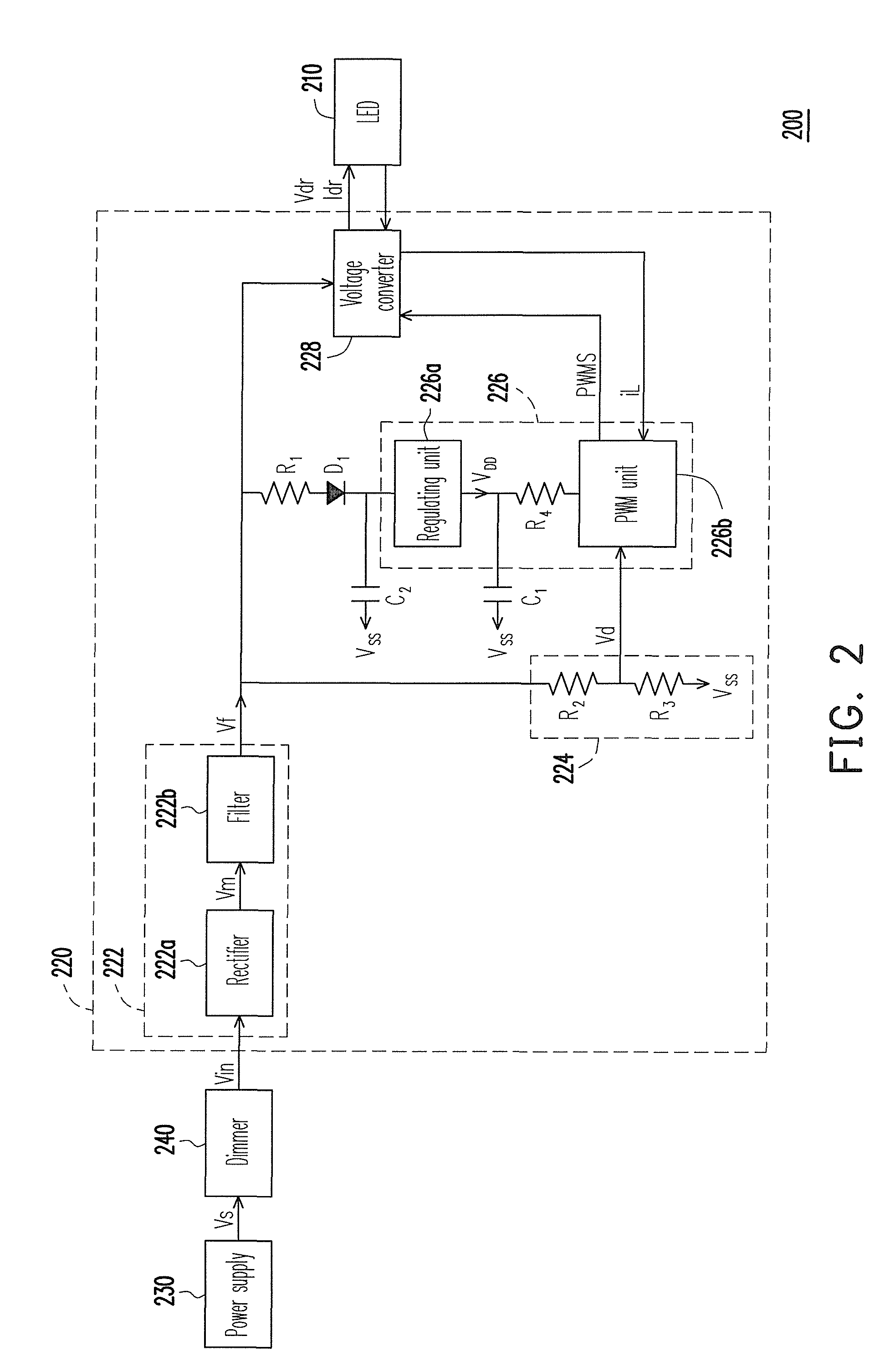
[0034]FIG. 2 is a diagram illustrating a lighting apparatus according to an embodiment of the present invention. Referring to FIG. 2, the lighting apparatus 200 includes a light emitting diode (LED) 210 and a driving circuit 220. The driving circuit 220 includes a rectifier unit 222, a voltage-dividing circuit 224, a control unit 226, a voltage converter 228, a resistor R1, a capacitor C2 and a diode D1. In the present embodiment, the lighting apparatus 200 can further include a power 230 and a dimmer 240, wherein the dimmer 240 receives an input voltage Vs from the power supply 230, and outputs an alternating current (AC) power Vin according to a conducting condition. In the present embodiment, the dimmer 240 can be implemented by a tri-electrode AC switch (TRIAC), though the present invention is not limited thereto. Moreover, illuminance values of a light source that is adjusted by the TRIAC dimmer are sequentially divided into nine grades of a maximum value, a first to a seventh ...


PUM


Abstract

A driving circuit of a light emitting diode (LED) includes a rectifier unit, a voltage-dividing circuit, a control unit, a voltage converter, a resistance and a capacitor. The rectifier unit rectifies an AC power to generate a first operation voltage. The voltage-dividing circuit generates a voltage-dividing signal. The control unit includes a regulating unit and a pulse width modulation (PWM) unit. An output terminal of the regulating unit is coupled to the PWM unit. The PWM unit outputs a PWM signal. The voltage converter adjusts a driving voltage and a driving current of the LED. The resistance is coupled between an output terminal of the regulating unit and a diode. The capacitor is coupled between a power input terminal of the regulating unit and a ground terminal. The PWM unit adjusts the PWM signal according to the voltage-dividing signal and a feedback signal output by the voltage converter.

Description

CROSS-REFERENCE TO RELATED APPLICATION[0001]This application claims the priority benefit of Taiwan application serial no. 98209248, filed on May 26, 2009. The entirety of the above-mentioned patent application is hereby incorporated by reference herein and made a part of specification.BACKGROUND OF THE INVENTION[0002]1. Field of the Invention[0003]The present invention relates to a driving circuit and a lighting apparatus. More particularly, the present invention relates to a driving circuit used for driving a light emitting diode, and a lighting apparatus using the same.[0004]2. Description of Related Art[0005]Regarding related techniques of a lighting apparatus, a dimmer is generally used for controlling a power supply, so that not only a light-emitting device (for example, a bulb) can be turned on / off, but also a light-emitting effect of the lighting apparatus can be fine-tuned. FIG. 1 is a diagram illustrating a conventional lighting apparatus. Referring to FIG. 1, the lighting ...

Claims


Application Information

Patent Timeline
Patent Type & Authority Patents(United States)
IPC IPC(8): H05B41/36H05B37/02
CPCH05B33/0815H05B33/0845H05B45/10A61P35/00H05B45/375
Inventor WANG, CHUN-HSIUNGCHEN, CHIH-TSUNGWANG, HAO-YUANLIU, YAO-SHENGHO, KWAN
Owner CAL COMP ELECTRONICS
Why Eureka
Try Eureka