Magnetic refrigerating device and magnetic refrigerating method

a magnetic refrigeration and refrigerating device technology, applied in the direction of magnets, magnet bodies, lighting and heating apparatus, etc., can solve the problems of ozone layer destruction or global warming, high operation cost, and large size of magnetic refrigeration systems,

Active Publication Date: 2012-01-24
KK TOSHIBA
View PDF16 Cites 108 Cited by
  • Summary
  • Abstract
  • Description
  • Claims
  • Application Information

AI Technical Summary

Benefits of technology

[0029]It is an object of the present invention, in view of the above-described problems relating to the magnetic refrigerating system near room temperature region, to provide a small and simple magnetic refrigerating device and a magnetic refrigerating method which do not require fluid flow such as liquid flow or gas flow in the heat transfer.
[0032]According to the aspects of the present invention, the magnetic refrigerating unit is configured so as to contain at least one stacking unit of the materials “A”, “B”, “a” and “b”, and the intended heat transfer is conducted from one end to the other end of the magnetic refrigerating unit by utilizing the repeated heat generation and heat insulation originated from the materials “A”, “B”, “a” and “b” when a magnetic field is applied to and removed from the magnetic refrigerating unit. Therefore, since the heat transfer can be conducted as a solid transfer via the constituent materials of the magnetic refrigerating unit, the magnetic refrigerating unit may not be cracked by the repeated pressure shock of the liquid transfer medium as the AMR type magnetic refrigeration.
[0036]The permanent magnet is a double-structured Halbach-type magnet composed of an inner Halbach-type magnet and an outer Halbach-type magnet, wherein the magnetic refrigerating unit is disposed in the bore space of the inner Halbach-type magnet. In this case, if only the inner Halbach-type magnet and the outer Halbach-type magnet are relatively shifted, a first magnetic field and a second magnetic field with the respective different intensities can be applied to the magnetic refrigerating unit. Namely, the first magnetic field and second magnetic field with the respective different intensities can be applied to the magnetic refrigerating unit only by rotating operation of the magnet. As a result, the thus generated heat can be transferred in the magnetic refrigerating unit and thus, the intended magnetic refrigeration can be realized by simple rotating operation without heat transfer medium and its drive mechanism.
[0037]In this case, preferably, the outer Halbach-type magnet is rotated while the relative position between the inner Halbach-type magnet and the magnetic refrigerating unit disposed in the bore space of the inner Halbach-type magnet is fixed. Therefore, the relative rotation can be easily conducted under the condition without the frictional heat generation between the inner Halbach-type magnet and the magnetic refrigerating unit disposed in the bore space of the inner Halbach-type magnet. As a result, the thus generated heat can be transferred in the magnetic refrigerating unit and thus, the intended magnetic refrigeration can be realized.
[0038]At least one of the inner Halbach-type magnet and the outer Halbach-type magnet may be composed of a plurality of Halbach-type magnets which are configured such that the direction of a magnetic field generated from an inner Halbach-type magnet is different from the direction of the magnetic fields generated from the other inner Halbach-type magnets. In this case, the plurality of Halbach-type magnets are stacked along a flow direction of heat generated. Therefore, the total magnetic torque can be reduced due to the fact that the magnetic torque generated from one set of magnetic refrigerating unit and magnet can be cancelled by the magnetic torques generated from another sets of magnetic refrigerating unit and magnet so that the motive energy load for rotating the outer Halbach-type magnet relatively for the inner Halbach-type magnet can be reduced.
[0040]According to the aspect of the present invention can be provided a small and simple magnetic refrigerating device without heat transfer medium and its drive mechanism and a magnetic refrigerating method which do not require fluid flow such as liquid flow or gas flow in the heat transfer.

Problems solved by technology

However, in the refrigeration technique using the gas compressing and expanding cycle such as a chlorofluorocarbon (CFC) or hydrochlorofluorocarbon (HCFC) or hydrofluorocarbon (HFC) gas, there are some problems relating to the ozone layer destruction or the global warming caused by the environmental exhaust of those gasses.
Therefore, the magnetic refrigeration system becomes complicated, grows in size and requires high operation cost in the same manner as the superconducting magnet.
The wet type magnetic refrigerating device using the liquid heat transfer medium has some disadvantages such as handling and complicated design.
In the case that the magnetic refrigerant is brittle, the magnetic refrigerant may be cracked by the repeated pressure shock.
In this case, fine powders may be generated due to the crack of the magnetic refrigerant so as to disturb the flow of the heat transfer medium and thus, to deteriorate the performance of the magnetic refrigerating system.
In this case, the flow path in the packed particles can not be maintained so as to increase the pressure loss of the heat transfer medium and thus, to deteriorate the refrigerating performance of the magnetic refrigerating system.
Even though the magnetic refrigerant can exhibit a large magneto-caloric effect, it becomes difficult to use the magnetic refrigerant if the magnetic refrigerant can not exhibit enough mechanical strength against the repeated pressure shock.
Therefore, when the permanent magnet is employed as a magnet in the AMR system, there are some disadvantages such as the large reduction of the intensity of the magnetic field, which is to be applied to the magnetic refrigerant accommodated in the AMR bed, originated inherently from the use of the permanent magnet and from the large demagnetization field due to the geometrical shape of the AMR bed which is restricted in design.

Method used


Image

  • Magnetic refrigerating device and magnetic refrigerating method
  • Magnetic refrigerating device and magnetic refrigerating method
  • Magnetic refrigerating device and magnetic refrigerating method

Examples


Embodiment Construction

[0057]Hereinafter, the present invention will be described in detail with reference to the drawings.

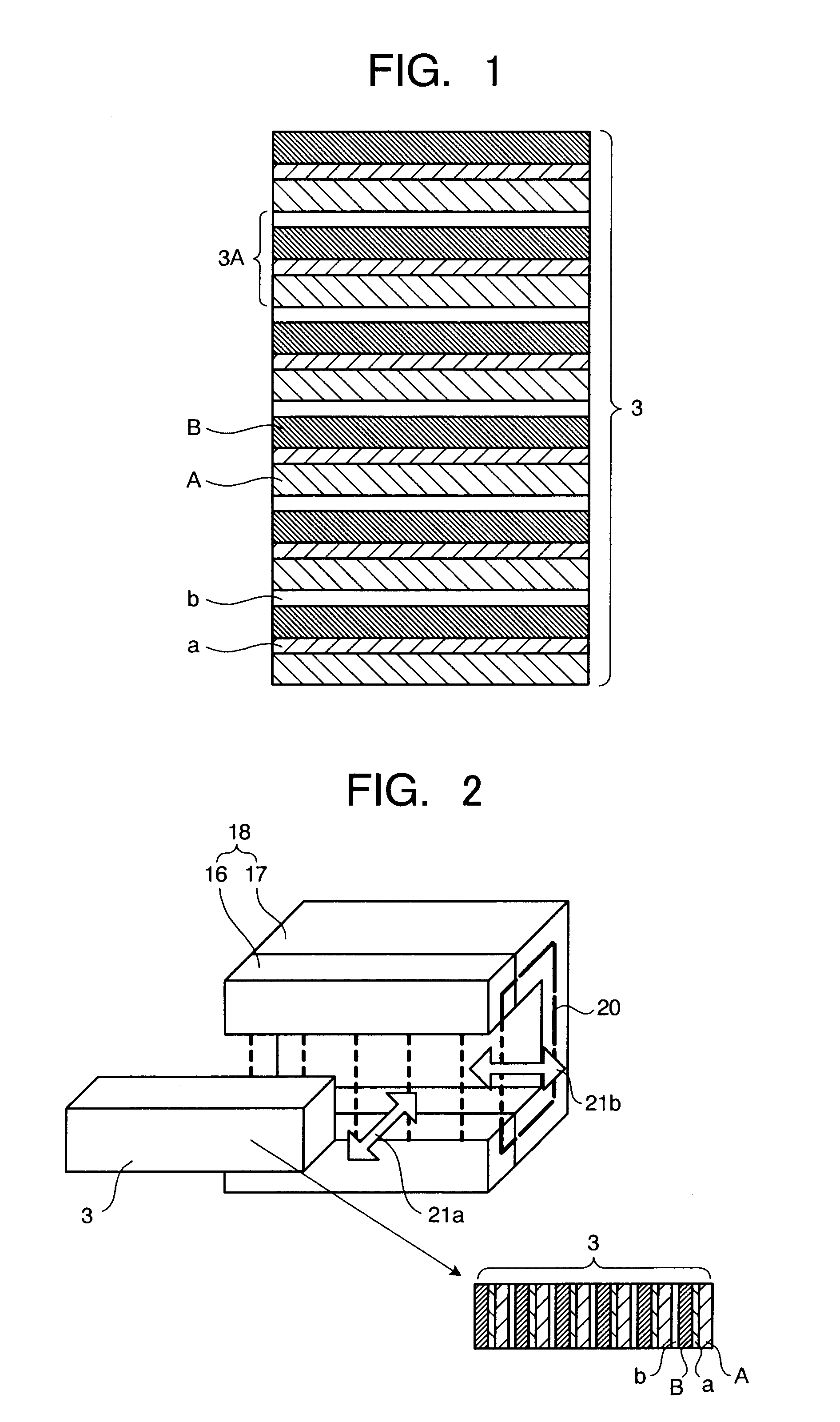
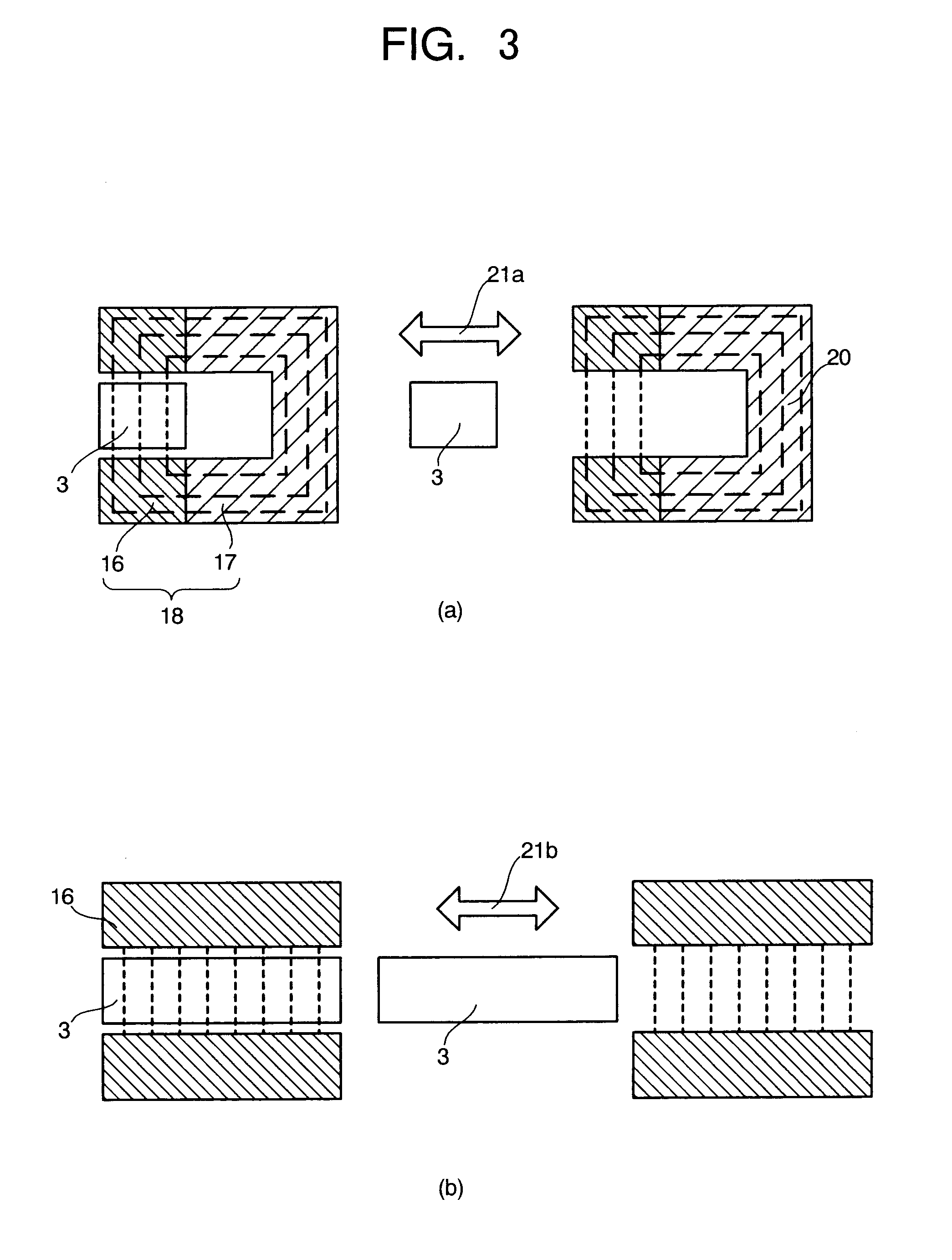
[0058]FIG. 1 is a schematic view illustrating the magnetic refrigerating device according to an embodiment of the present invention. FIGS. 2 and 3 are structural views illustrating concrete embodiments relating to the magnetic refrigerating device in FIG. 1, respectively. FIG. 4 is an explanatory view for the magnetic refrigerating heat cycle in the magnetic refrigerating device in FIG. 1. Herein, FIG. 2 is a perspective view illustrating the concrete embodiment of the magnetic refrigerating device in this embodiment.

[0059]Like or corresponding components are designated by the same reference numerals throughout the drawings.

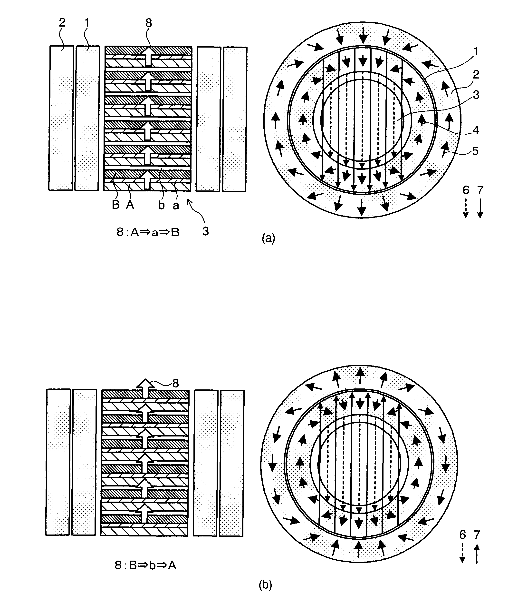
[0060]In FIG. 1, a magnetic refrigerating unit 3 of the magnetic refrigerating device in this embodiment is composed of magnetic materials “A” and “B” and heat conductive materials “a” and “b”. The magnetic material “A” exhibits the magneto-caloric effect that the ...


PUM

PropertyMeasurementUnit
diameteraaaaaaaaaa
magnetic fieldaaaaaaaaaa
temperatureaaaaaaaaaa

Abstract

A magnetic refrigerating device includes: a magnetic refrigerating unit including a magnetic material “A” exhibiting a magneto-caloric effect that the temperature of the material “A” is increased by the application of a magnetic field and the temperature of the material “A” is decreased by the removal of a magnetic field, a magnetic material “B” exhibiting a magneto-caloric effect that the temperature of the material “B” is decreased by the application of a magnetic field and the temperature of the material “B” is increased by the removal of a magnetic field, a heat conductive material “a” exhibiting higher heat conductivity under the application of a magnetic field and lower heat conductivity under the removal of a magnetic field, and a heat conductive material “b” exhibiting lower heat conductivity under the application of a magnetic field and higher heat conductivity under the removal of a magnetic field, wherein the magnetic refrigerating unit is configured so as to include at least one layered structure denoted by “AaBb” or “AbBa”; and a magnetic field-applying means to apply a magnetic field to the magnetic refrigerating unit.

Description

CROSS-REFERENCE TO RELATED APPLICATIONS[0001]This application is based upon and claims the benefit of priority from the prior Japanese Patent Application No. 2006-265832, filed on Sep. 28, 2006; the entire contents of which are incorporated herein by reference.BACKGROUND OF THE INVENTION[0002]1. Field of the Invention[0003]The present invention relates to a magnetic refrigeration device and a magnetic refrigeration method which can simplify the driving mechanism by conducting the heat transfer utilizing the solid heat conduction not requiring a liquid medium or a gaseous medium for the heat transfer.[0004]2. Description of the Related Art[0005]When the intensity of magnetic field to be applied is changed for a certain magnetic material, the temperature of the magnetic material also changes, which is called as a “magneto-caloric effect”. Physically, the degree of freedom of magnetic spins (electrons bearing the magnetic property) in the magnetic material is changed with the change of...

Claims


Application Information

Patent Timeline
Patent Type & Authority Patents(United States)
IPC IPC(8): F25B21/00H01F7/02
CPCF25B21/00F25B2321/0021F25B2321/0023Y02B30/66Y02B30/00
Inventor SAITO, AKIKOKOBAYASHI, TADAHIKOTSUJI, HIDEYUKIIWASAKI, HIDEOHISANO, KATSUMIKOGA, AKIHIROKASAHARA, AKIHIROTAKAHASHI, TAKUYA
Owner KK TOSHIBA
Why Eureka
Try Eureka