
Tissue refining device

a tissue refining and tissue technology, applied in the field of tissue refining devices, can solve the problems of reducing the likelihood of tissue rejection, affecting the quality of tissue collection, so as to facilitate the processing of tissue collection

Active Publication Date: 2012-01-24
SUMMIT MEDICAL LLC
View PDF41 Cites 68 Cited by
  • Summary
  • Abstract
  • Description
  • Claims
  • Application Information

AI Technical Summary

Benefits of technology

[0022]Another aspect of the present invention is the introduction of a tissue collection syringe and associated tubing coupled to t

Problems solved by technology

However, the adipose cells are relatively delicate and the number of steps and length of time required to separate and process the harvested tissue prior to re-introduction into the patient contributes directly to the success of the operation and decreases the likelihood the tissue will be rejected.
This technique takes less time; however, it often requires sedation with an IV or general anesthesia.
Unfortunately, the nature of liposuction procedures preclude easy tissue isolation after initial harvest, especially on a large scale, because the volume and / or viscosity of the extracted liposuction effluent also contains unwanted components such as oil, blood and anesthetic solution.
Currently, there are no standard techniques, methods, or devices that exist for the simple, large scale isolation and refinement of liposuction-harvested adipose tissue.
Although a number of specialized canulas, needles and methods for tissue harvest and preparation exist, these techniques are tedious and inefficient.
This adds to the complexity of the overall training process as well.
While providing a useful multi-stage filling station, the number of steps using these Shipped devices results in a cumbersome harvesting and re-injection process that may be improved upon.
However, there is no means to access the collected tissue specimens with first removing the lid resulting in an increased exposure to the surrounding air.

Method used


Image

  • Tissue refining device
  • Tissue refining device
  • Tissue refining device

Examples


Embodiment Construction

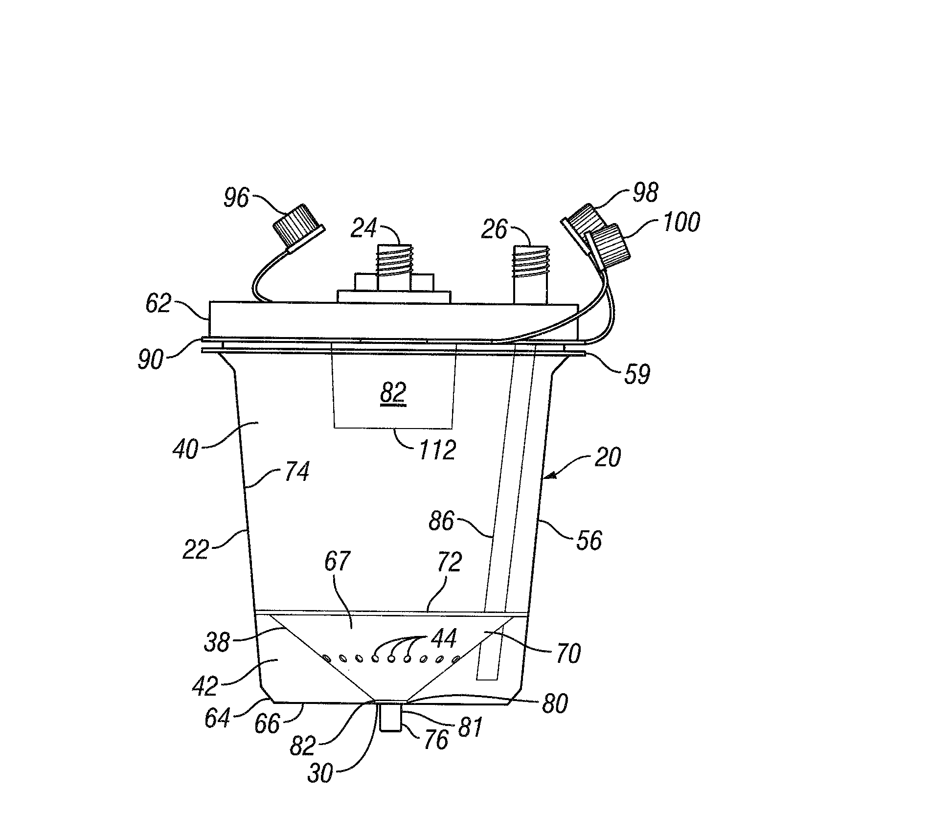
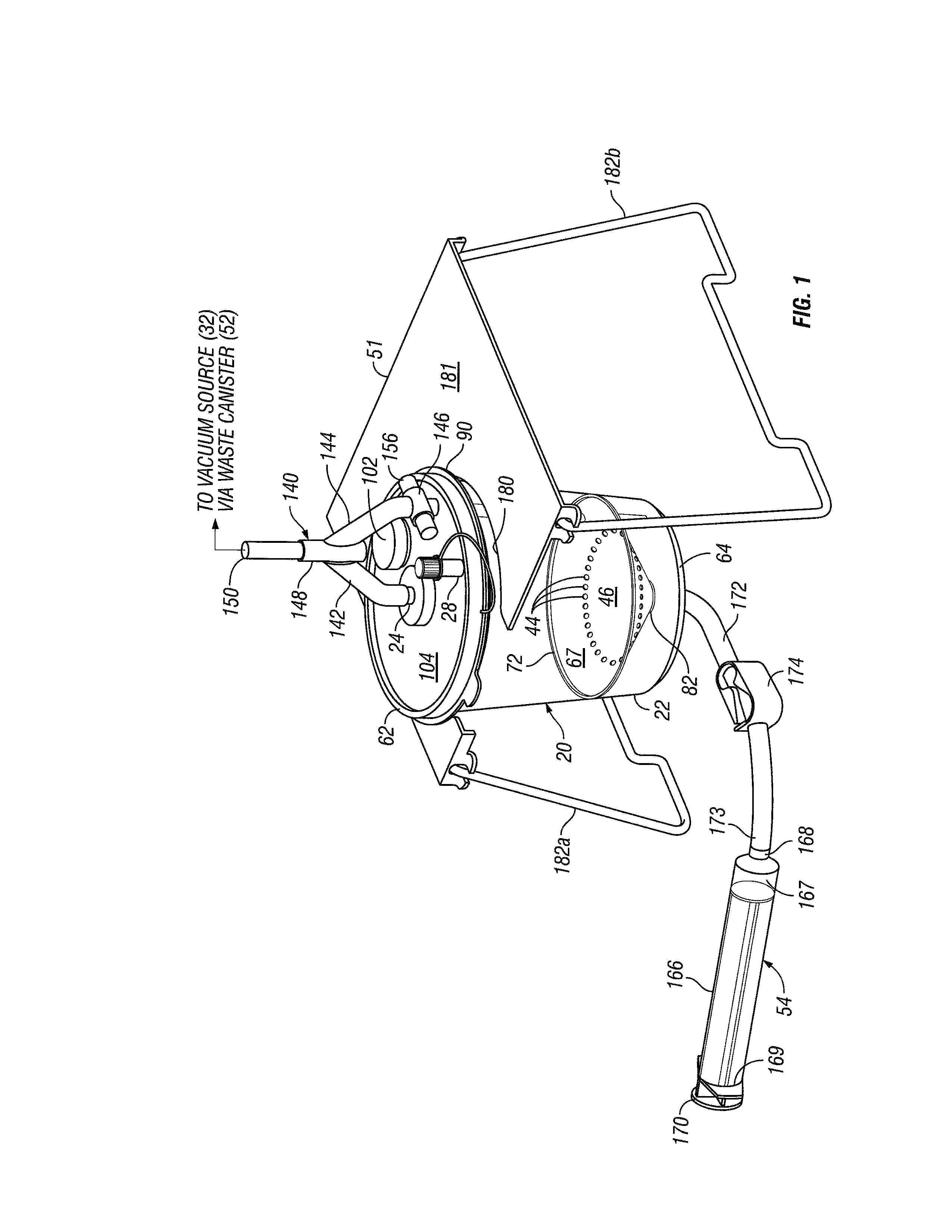
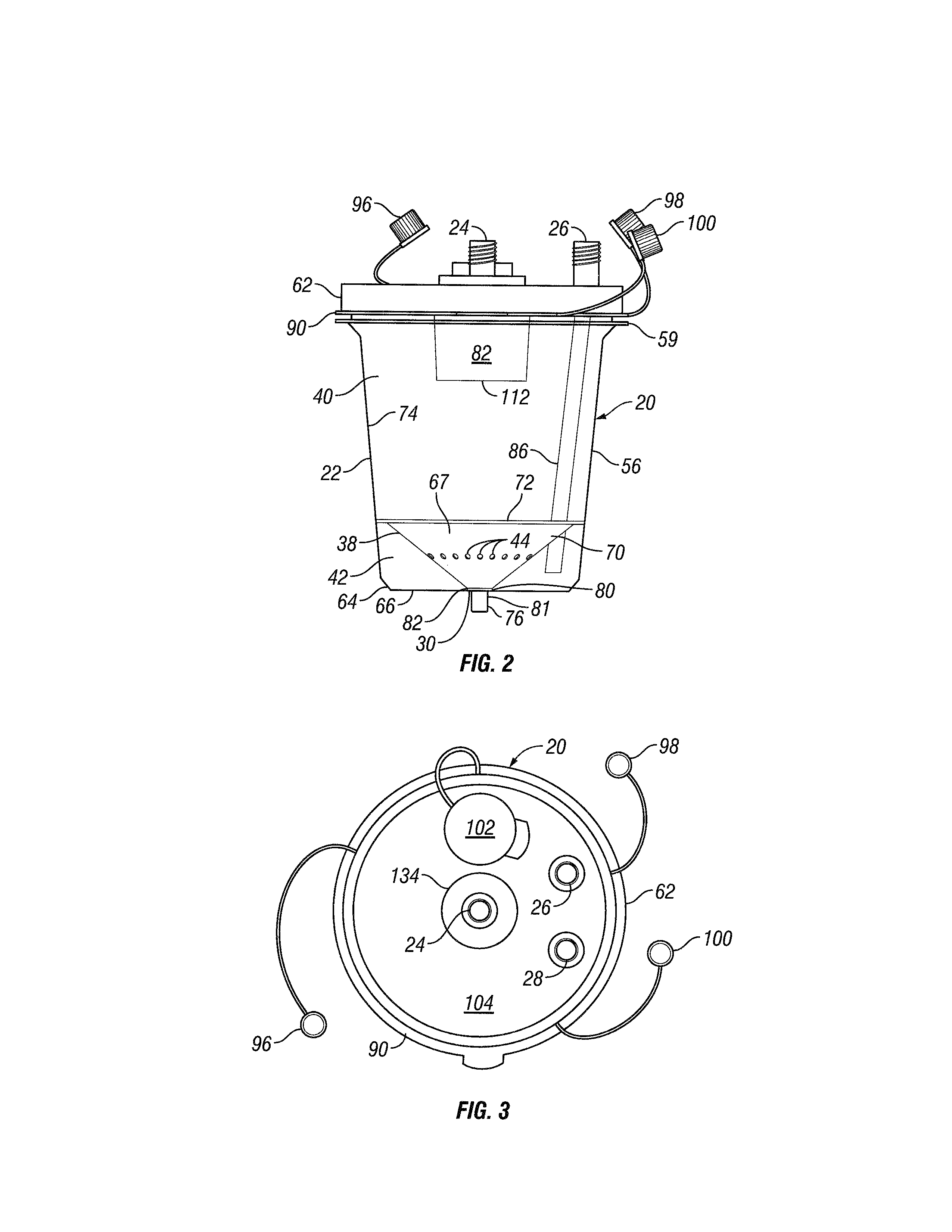
[0047]Referring now to FIGS. 1-7, an exemplary embodiment of a tissue refining device, generally designated 20, and in accordance with the principles of the present invention, is illustrated. Referring specifically now to the views in FIGS. 1-5, in general terms, the tissue refining device 20 includes a canister body 22 that includes a set of four ports, namely, a vacuum port 24, a fluid evacuation port 26, a tissue harvesting port 28, and a tissue retrieval port 30. The vacuum and fluid evacuation ports may be operatively coupled to one or more vacuum sources 32 (FIGS. 16A-C) while the tissue harvesting port may be operatively coupled to a conventional harvesting device 55 (FIG. 16A) to direct a quantity of tissue 36 (FIGS. 12-15 and 16A-C) retrieved by the harvesting device into the canister body when suction or a negative pressure is applied to the vacuum port by the vacuum source. The tissue refining device also includes a separator element 38 dividing the canister body into an ...


PUM


Abstract

A device for use in a system or method of collecting and processing aspirated tissue received from a harvesting device is provided by a canister body having a vacuum port and an evacuation port operable to be placed in communication with a vacuum source, a tissue harvesting port for directing tissue into the canister body received from the harvesting device under suction, and a separator element dividing the canister body into an upper vacuum chamber in communication with the vacuum port and the tissue harvesting port and a lower vacuum chamber in communication with the evacuation port, the separator element including a plurality of apertures enabling fluid to pass between the chambers while restricting tissue from doing the same and a depression with a channel leading to a tissue retrieval port to facilitate processed tissue collection.

Description

BACKGROUND[0001]1. Field of the Invention[0002]The present invention relates to fluid and tissue collection devices and more specifically to devices for collecting and processing aspirated adipose tissue for use in autologous adipose tissue implantation procedures.[0003]2. Background Art[0004]Liposuction, a popular type of cosmetic surgery also known as lipoplasty, liposculpture and suction assisted body contouring, is a technique for removing adipose tissue by inserting a hollow tube, or canula, through the skin and connecting it to a vacuum pump to suction out a quantity of fatty tissue. The procedure may be used to remove unwanted deposits of excess fat, to improve body appearance, and to smooth irregular or distorted body shapes, also known as body sculpting. Liposuction may be useful for contouring almost any area of the body including under the chin, neck, cheeks, upper arms, breasts, abdomen, buttocks, hips, thighs, knees, calves, and ankle areas.[0005]A liposuction machine a...

Claims


Application Information

Patent Timeline
IPC IPC(8): A61M1/00
CPCA61M1/0001A61M1/0056C12M47/04A61M2202/08A61M2209/082A61M1/79A61M1/892
Inventor JORDAN, DONNELL MARKKIMSEY, II, MELBOURNE
Owner SUMMIT MEDICAL LLC
Learn More