
Buoyant in-stream hydro turbine

Active Publication Date: 2012-01-24
GUTEKUNST BRENT LEE
View PDF11 Cites 10 Cited by
  • Summary
  • Abstract
  • Description
  • Claims
  • Application Information

AI Technical Summary

Benefits of technology

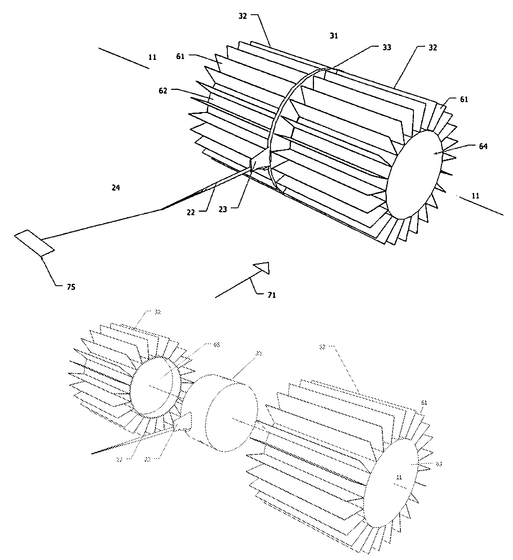
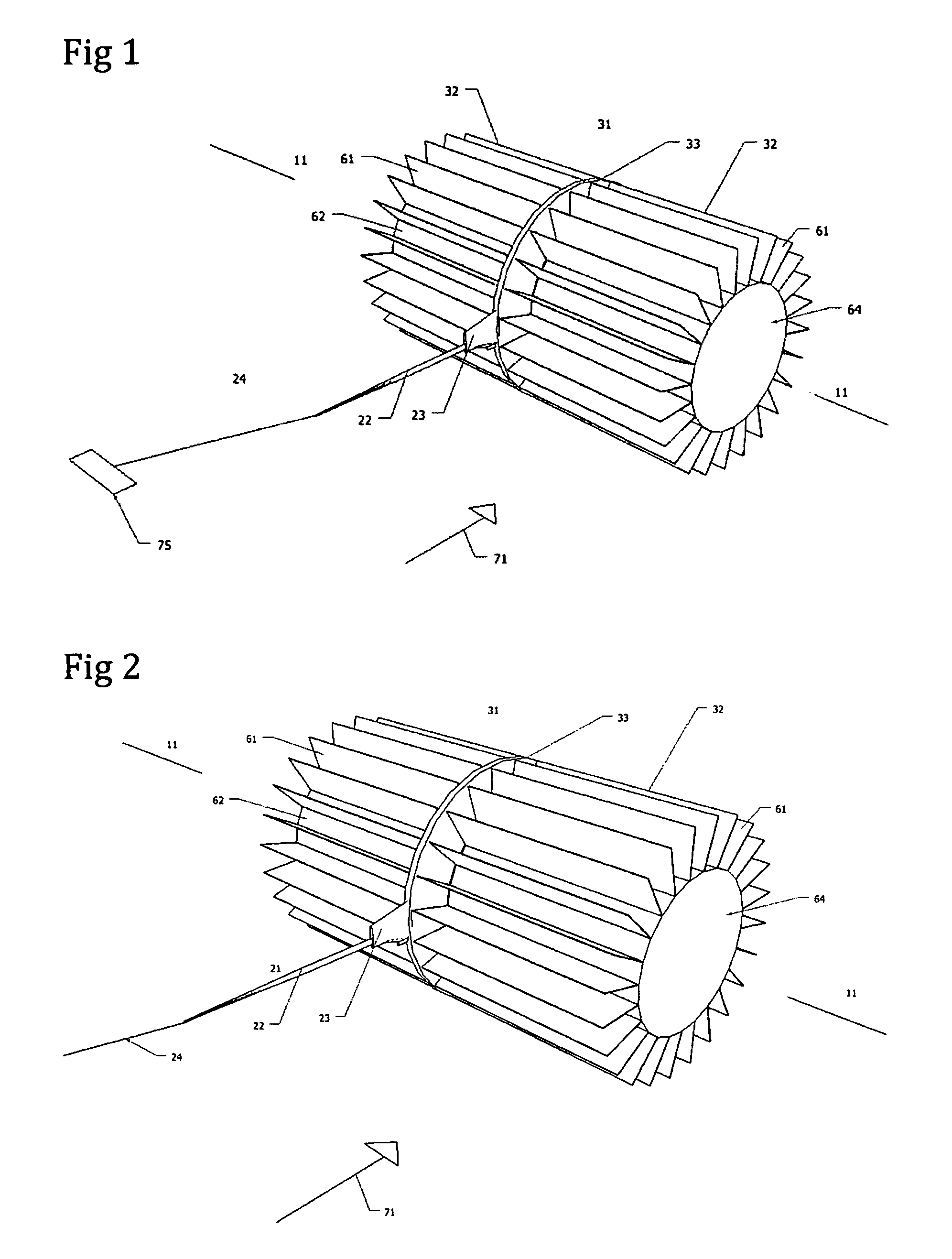
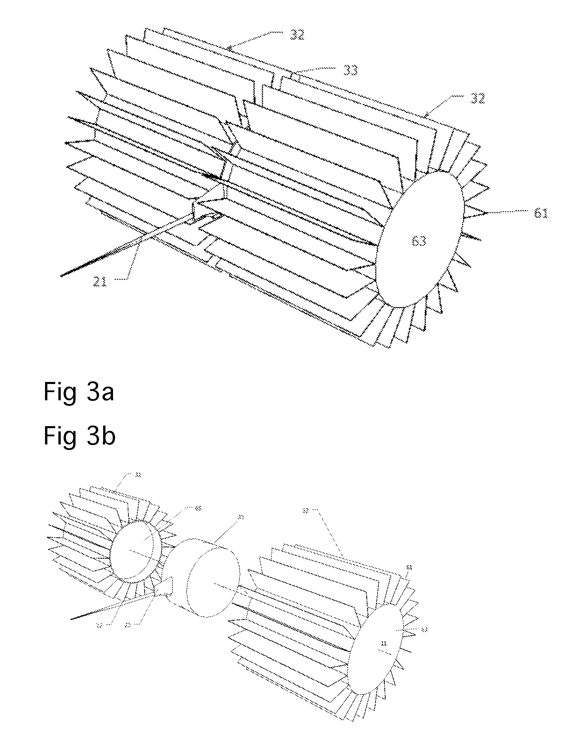
[0028]This invention and associated embodiments pertain to a buoyant in-stream turbine. One embodiment of the invention comprises a buoyant rotor substantially enclosing a driven component and support component. In use, the device is placed in a body of moving water and held in desired location within the water by a tether. The tether has the means for transporting energy, materials or communications individually or in combination to and from the device and its anchorage. The moving water impacts the invention with kinetic energy and in turn, the build-up of hydrostatic pressure. This combination exerts force on the rotor's blades causing it to rotate. The rotational energy of the rotor is then transferred to the driven components, where it is utilized to create electricity or some other form of mechanical energy. The driven component is encircled by a ridge, which reduces the risk of entanglement with debris, serves as a vane in the water's current to maintain the turbines position perpendicular to the direction of the current, and in turn, increases the available hydrostatic pressure.

Problems solved by technology

These articulated buoyant members contribute drag on the device, and do not contribute to the device's efficiency in capturing the kinetic energy delivered to the water powered device.
This too, fails to effectively utilize efficiently the Hydro kinetic energy placed upon, and delivered to, the device.
The placement of the generator within the drum of the water wheel, limits the flexibility of adjusting the device for various current conditions, and requires multiple attachments that increase the device's risk of damage or entanglement in debris.

Method used


Image

  • Buoyant in-stream hydro turbine
  • Buoyant in-stream hydro turbine
  • Buoyant in-stream hydro turbine

Examples


Embodiment Construction

[0061]While the invention is susceptible to various modifications and alternative constructions, certain illustrated embodiments thereof have been shown in the drawings and will be described below in detail. It should be understood, however, that there is no intention to limit the invention to the specific form disclosed, but, on the contrary, the invention is to cover all modifications, alternative constructions, and equivalents falling within the spirit and scope of the invention as defined in the claims.

[0062]The present invention is a buoyant turbine for generating power from water currents. In FIG. 1, a perspective view of the first embodiment of the present invention identified by reference numeral 31, is shown in a current in a body of water, such as a stream, river, or tidal flow identified by reference numeral 72. The current flows in the direction of the arrow 71. The invention 31, includes a water driven rotor 32, which drives the Driven Component, indicated generally by ...


PUM


Abstract

A buoyant hydro turbine(31) for capturing and utilizing energy in the currents of flowing water. A driven component(33) produces electricity or other energy is coupled to and supported by a buoyant rotor(64), increasing efficiency and eliminating the need for an independent supporting structure. Tethered in flowing water, the current(71) rotates the rotors(32) and transfers rotatable energy to the central driven component(33) where electricity or other mechanical work is produced. A number of embodiments are adapted for optimizing and maintaining positioning in a stream of moving water. Additional embodiments optimizing the efficiency and effectiveness of the turbine in capturing and utilizing the current's kinetic energy as well as hydrostatic pressure.

Description

CROSS-REFERENCE TO RELATED APPLICATIONS [0001]Not ApplicableFEDERALLY SPONSORED RESEARCH [0002]Not ApplicableSEQUENCE LISTING OR PROGRAM [0003]Not ApplicableBACKGROUND[0004]1. Field[0005]The invention relates to buoyant water powered device for producing electricity or other mechanical work in areas of flowing water.[0006]2. Information[0007]This invention relates to a device that is designed to capture energy from existing currents of water and is particularly designed to operate while floating in-stream.[0008]One of this planet's most common and readily available source of renewable energy is moving water. The power of Hydro kinetic energy is well known and well documented. It is abundant and is found in the vast quantities in every stream, river or other moving bodies of water. Its use and utilization is a function of economic and ecological constraints.[0009]The most familiar methods for the utilization of this energy require dams, impounds or major civil works to contain and re...

Claims


Application Information

Patent Timeline
IPC IPC(8): F03B13/10
CPCF03B17/063F05B2240/40F05B2240/93Y02E10/28Y10S415/906Y02E10/30Y02E10/20
Inventor GUTEKUNST, BRENT LEE
Owner GUTEKUNST BRENT LEE
Learn More