Dual band circularly polarized feed

a circular polarized feed and dual band technology, applied in the direction of simultaneous aerial operations, electrically short antennas, antennas, etc., can solve the problems of destructive interference and cancellation

Active Publication Date: 2012-01-24
BALL AEROSPACE & TECHNOLOGIES
View PDF21 Cites 40 Cited by
  • Summary
  • Abstract
  • Description
  • Claims
  • Application Information

AI Technical Summary

Benefits of technology

[0009]In accordance with embodiments of the disclosed invention, the pair of radiating elements or patches are stacked with respect to one another. A first feed network comprises a 90° hybrid that feeds the first patch through first and second antenna element ports at 0° and 90°, and the second feed network comprises a 90° hybrid that feeds the second patch through first and second antenna element ports at 0° and 90°. Moreover, the signals provided to the patches can be circularly polarized. The first and second antenna element ports feeding the first patch and the first and second antenna element ports feeding the second patch are arranged such that the distance between the first antenna element port of the first feed network and the first antenna element port of the second feed network is equal to the distance between the second antenna element port of the first feed network and the second antenna element port of the second feed network. The effect of coupling between the feeds at the feed input / output ports is negligible, because the two paths over which the coupled signal travels are 180° out of phase with one another at the input / output port of the feed network to which the signals are coupled, resulting in destructive interference and cancellation. Accordingly, unwanted energy from coupling between the feeds, which would normally cause interference, is removed, negating the effect of the coupling between the superimposed patches.

Problems solved by technology

The effect of coupling between the feeds at the feed input / output ports is negligible, because the two paths over which the coupled signal travels are 180° out of phase with one another at the input / output port of the feed network to which the signals are coupled, resulting in destructive interference and cancellation.
Accordingly, unwanted energy from coupling between the feeds, which would normally cause interference, is removed, negating the effect of the coupling between the superimposed patches.

Method used


Image

  • Dual band circularly polarized feed
  • Dual band circularly polarized feed
  • Dual band circularly polarized feed

Examples


Embodiment Construction

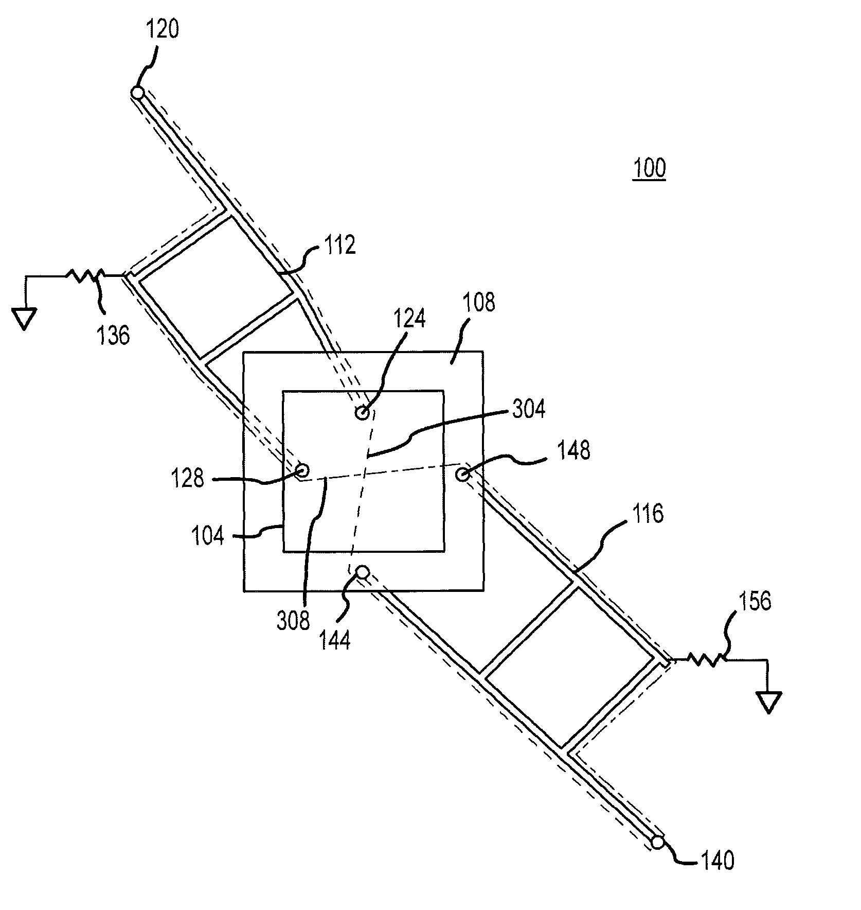
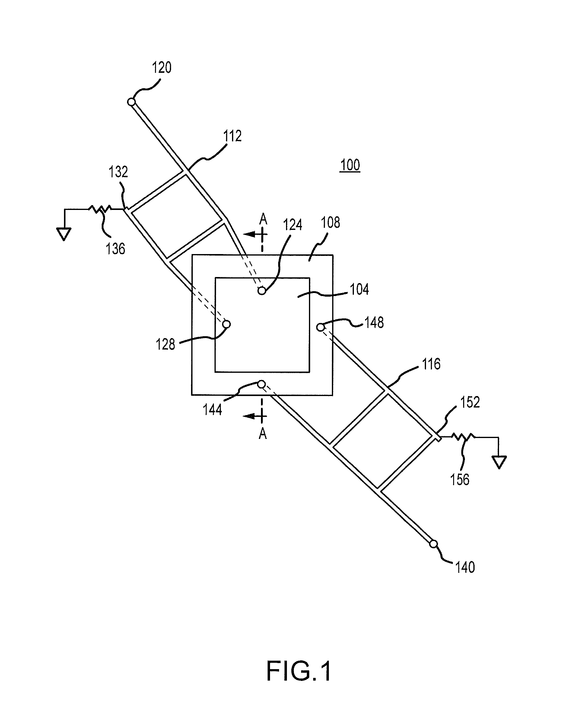
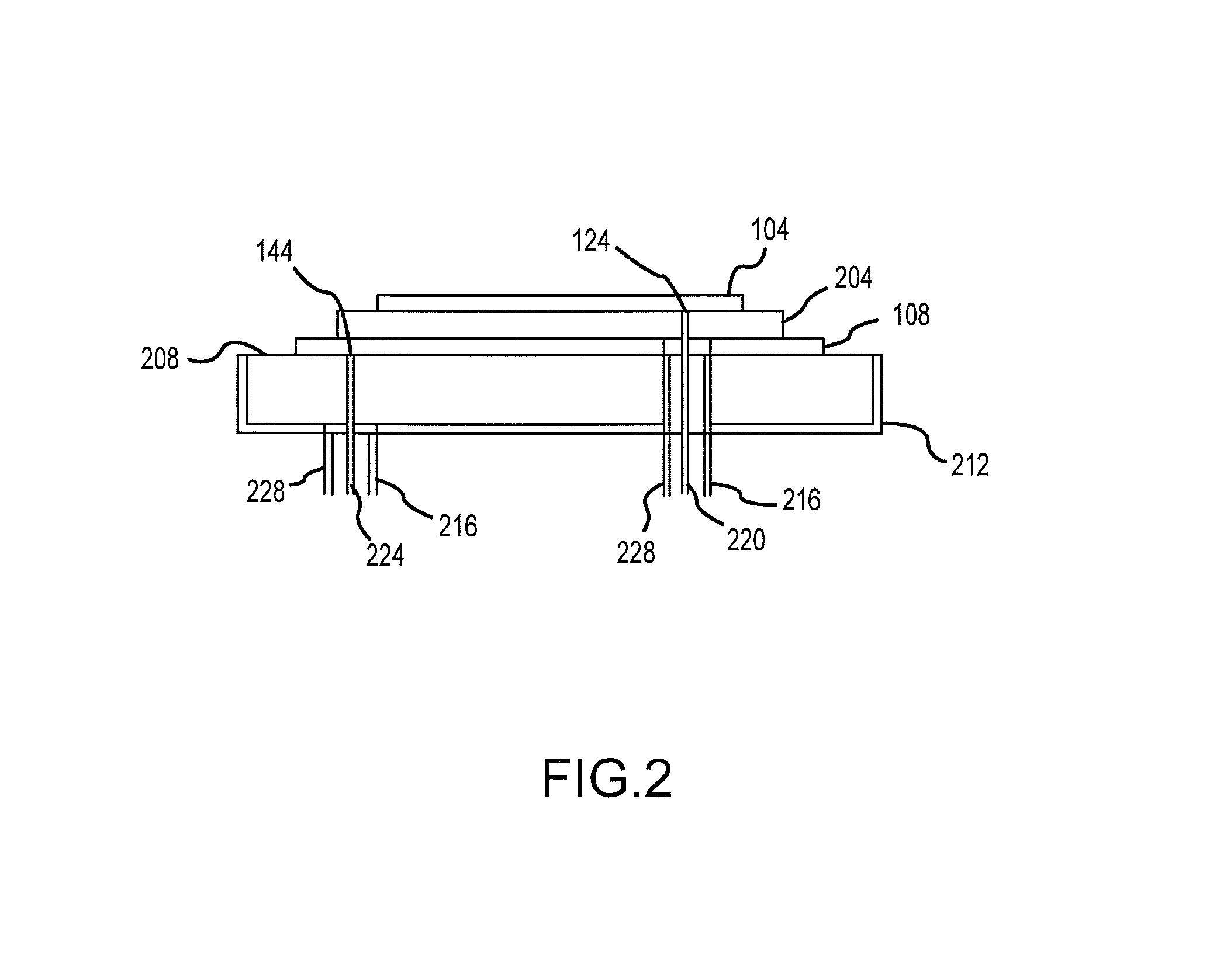
[0017]FIG. 1 depicts an antenna system 100 in accordance with embodiments of the disclosed invention in plan view. The antenna system 100 generally includes first 1011 and second 108 radiating elements or patches 104, 108. As shown, the first patch 104 is superimposed over or stacked with respect to the second patch 108. Moreover, as can be appreciated by one of skill in the art, the first patch 104 is dimensioned for use in connection with a first, relatively high (compared to the second patch 108) frequency or frequency band (i.e., a relatively short wavelength or range of wavelengths). The second patch 108 is dimensioned for use in connection with a second, relatively low (compared to the first patch 104) frequency or frequency band (i.e., a relatively long wavelength or range of wavelengths). Accordingly, the antenna system 100 is a dual band system. As illustrated, the first patch 104 and the second patch 108 can comprise round elements that are concentric with respect to one a...


PUM


Abstract

Dual band antenna systems and methods providing isolation between bands are provided. The system includes a pair of superimposed antenna radiating elements, each of which is connected to an associated feed network. The feed networks may comprise a quadrature hybrid networks. Coupling paths between the first and second feed networks are arranged such that a first component of a first signal coupled from a first feed network to a second feed network will be 180° out of phase with a second signal component of the first signal coupled from the first feed network to the second feed network at the input/output of the second feed network. The resulting destructive interference results in isolation between the bands.

Description

FIELD[0001]A dual band antenna system is provided. More particularly, a dual band isolated feed for an antenna system that includes a pair of radiating elements is provided.BACKGROUND[0002]Dual band antennas have many applications. For example, systems in which transmit and receive modes are separated in bandwidth are in use or being proposed.[0003]In systems that feature dual band operation, it is desirable to provide a single antenna aperture that supports both the transmit and receive modes. In order to operate an antenna at multiple frequency bands, diplexers have been used. In concept, diplexers separate the bandwidth of a wide band radiating structure into two narrower bands. Diplexers typically comprise filters that selectively feed low and high frequency radiating elements, and can be difficult and expensive to implement. In addition, diplexers can introduce losses, take up a significant amount of space, and add complexity and mass to an antenna assembly. Moreover, it is dif...

Claims


Application Information

Patent Timeline
Patent Type & Authority Patents(United States)
IPC IPC(8): H01Q3/22H01P1/165
CPCH01Q5/40H01Q9/0414
Inventor ALBERS, LUKE J.
Owner BALL AEROSPACE & TECHNOLOGIES
Why Eureka
Try Eureka