Vibrating micromechanical sensor of angular velocity

a micromechanical sensor and vibration technology, applied in the direction of acceleration measurement using interia force, turn-sensitive devices, instruments, etc., can solve the problems of limiting the dynamic of the signal, and reducing the accuracy of the signal

Active Publication Date: 2012-01-31
MURATA MFG CO LTD
View PDF10 Cites 14 Cited by
  • Summary
  • Abstract
  • Description
  • Claims
  • Application Information

AI Technical Summary

Benefits of technology

[0011]The objective of the invention is to provide such an improved vibrating sensor of angular velocity, which enables reliable measuring with a good performance, particularly in solutions with a small vibrating sensor of angular velocity, and in which the compensation for the quadrature signal is implemented by mechanical design without electric compensation, or, alternatively, in combination with the electric compensation methods mentioned above.
[0013]Preferably, one corner of the spring structure is etched off. Alternatively, one or more compensation groove is etched into the spring structure. Further, alternatively, one or more compensation cavity is etched into the spring structure. Further, alternatively, one or more compensation groove or compensation cavity is etched into at least one attachment spot for the spring structure. Further, preferably, the compensation grooves or the compensation cavities are suitably dimensioned such, that they effectively straighten the end portion of a skewed spring.
[0015]Preferably, the spring structure is designed to be asymmetric such, that the coupling from one mode of motion to another, conveyed by the spring, cancels or alleviates the coupling caused by non-ideality due to an inclination relative to the perpendicular to the disk of the groove of the DRIE etching process.
[0017]Preferably, the etching mask is designed such, that it compensates for non-idealities occurring over the surface of the disk, caused by the manufacturing process. Preferably the DRIE etching technique (DRIE, Deep Reactive Ion Etching) is used in the manufacturing. Preferably, in the manufacturing, non-idealities of the DRIE etching process are utilized, such as the ARDE effect (ARDE, Aspect Ratio Dependent Etch rate). Preferably, a two-stage DRIE etching process is utilized in the manufacturing, by means of which the depth of the etched groove or cavity can be suitably dimensioned.

Problems solved by technology

One of the most significant problems in micromechanical vibrating sensors of angular velocity is the so called quadrature signal, which is caused by poor dimensional precision in the structures.
In resonators manufactured using the means of micromechanics, there may be found tolerance errors in the perpendicularity of the directions of motion, which in the detection of the sensor of angular velocity cause a signal, called the quadrature signal, of a magnitude, at worst, hundreds of times larger than the angular velocity signal corresponding to the maximum value of the output scale.
However, being significantly larger than the signal to be measured, it restricts the dynamics of the signal.
Another big disadvantage of the quadrature signal is, that it, if left uncompensated for, significantly degrades the stability of the zero point of the sensor, due to phase shifts in the electronic signals as, for example, the temperature changes.
Compensation by means of electric forces constitutes a challenge to the sensor's electronics.

Method used


Image

  • Vibrating micromechanical sensor of angular velocity
  • Vibrating micromechanical sensor of angular velocity
  • Vibrating micromechanical sensor of angular velocity

Examples


Embodiment Construction

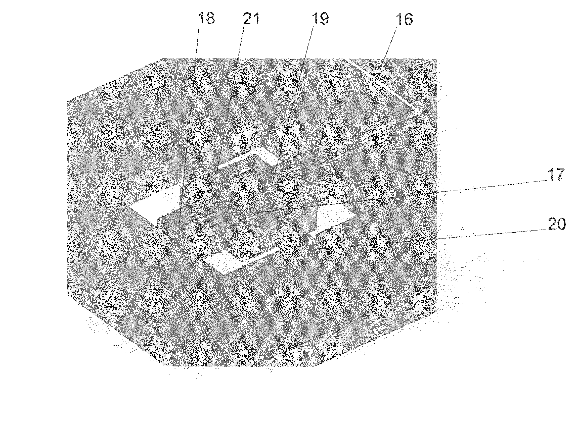
[0030]In a vibrating sensor of angular velocity according to the invention, the primary motion to be activated is the vibration of at least one seismic mass and an associated moving electrode. In addition to the primary motion, the seismic mass possesses another degree of freedom in relation to a detection axis essentially perpendicular to the primary motion.

[0031]Further, the sensor of angular velocity according to the invention comprises a seismic mass and an associated moving electrode, which mass is supported to the frame of the sensor component by means of a spring structure.

[0032]The moving electrode in the primary motion mode of the vibrating sensor of angular velocity according to the invention is activated into vibration. Thus, the coupling caused by the Coriolis force activates the detection motion mode. The motion axes of the primary motion mode and the detection motion mode, or the detection motion modes, are essentially perpendicular to each other. Due to the known non-...


PUM

PropertyMeasurementUnit
angular velocityaaaaaaaaaa
degree of freedomaaaaaaaaaa
Aspect Ratioaaaaaaaaaa

Abstract

The invention relates to measuring devices to be used in the measuring of angular velocity and, more precisely, to vibrating micromechanical sensors of angular velocity. In a sensor of angular velocity according to the invention, a mass is supported to the frame of the sensor component by means of an asymmetrical spring structure (1), (2), (3), (4), (22), (24) in such a way, that the coupling from one mode of motion to another, conveyed by the spring (1), (2), (3), (4), (22), (24), cancels or alleviates the coupling caused by the non-ideality due to the skewness in the springs or in their support. The structure of the sensor of angular velocity according to the invention enables reliable measuring with good performance, particularly in small vibrating micromechanical solutions for sensors of angular velocity.

Description

FIELD OF THE INVENTION[0001]The invention relates to measuring devices to be used for measuring angular velocity and, more precisely, to vibrating micromechanical sensors of angular velocity. The object of the invention is to provide an improved sensor structure enabling reliable measuring with good performance, particularly in small size vibrating micromechanical solutions for sensors of angular velocity.BACKGROUND OF THE INVENTION[0002]In measuring angular velocity, the principle of the method of measuring based on a vibrating sensor of angular velocity has proved to be simple and reliable. In a vibrating sensor of angular velocity, a certain known primary motion is induced and maintained in the sensor. The desired motion to be measured by means of the sensor is then detected as a deviation of the primary motion.[0003]An external angular velocity in a direction perpendicular to the resonators' direction of motion acting on the sensor induces a Coriolis force in the seismic mass in...

Claims


Application Information

Patent Timeline
Patent Type & Authority Patents(United States)
IPC IPC(8): G01C19/00G01P15/08G01C19/5712
CPCG01C19/5712Y10T29/49002G01C19/56G01P15/08
Inventor KLEMETTI, PETRINERA, KAISALIPSANEN, ANTTIBLOMQVIST, ANSSITORKKELI, ALTTI
Owner MURATA MFG CO LTD
Why Eureka
Try Eureka