
Triple-function vehicle safety sensor system

a safety sensor and triple-function technology, applied in the field of triple-function vehicle safety sensor systems, can solve the problems of increasing the likelihood of detecting potential hazards, reducing the likelihood of falsely reporting objects that are not hazard, etc., and achieves enhanced forward object tracking systems, improved detection, and broadening the field of view.

Inactive Publication Date: 2012-01-31
EPSILON LAMBDA ELECTRONICS CORP
View PDF5 Cites 25 Cited by
  • Summary
  • Abstract
  • Description
  • Claims
  • Application Information

AI Technical Summary

Benefits of technology

[0012]The vehicle safety sensor system (VSSS) of this invention includes a three-dimensional (3D) radar object tracking system for vehicular forward object detection. This forward object tracking system is enhanced by additional video object identification and validation (visibility permitting). These improvements then are further enhanced by use of redundant 3D forward sensors, one on the driver-side and one on the passenger-side of the vehicle. The use of two forward sensors, one on each side, broadens the field-of-view at short range improving the detection, for example of vehicles that cut-in close to the host vehicle. At a longer distance, where the antenna patterns of the two forward radar / video sensors share a common field-of-view, the outputs of the two [VSS] sensors are compared by a [VSSS] system processor to provide redundant detection of objects. This feature thereby increases the likelihood of detecting potential hazards and decreases the likelihood of falsely reporting objects that are not a hazard. Independent video sensors are provided on each side of the vehicle using both side / rear looking and downward looking video cameras for providing side / rear and downward looking views. These side / rear views on both sides of the vehicle are used for object validation when combined with output of side / rear radar sensors. The downward views are used, together with the forward video camera views on both sides of the vehicle for detection of lane markers as part of the lane departure detection means.
[0013]These innovations and enhancements for the three sensor functions can be achieved at affordable cost, compared to the use of separate sensors, because the total number of sensor units is reduced to only two and, thereby, the cost of installation on the vehicle is correspondingly reduced. Further, potential installation cost reduction may be provided by the use of wireless connectivity (such as blue tooth wireless) among the driver-side VSS sensor unit, the passenger-side VSS sensor unit and the driver control module. The VSSS system processor can be co-located at, or combined with, the driver VSS side or passenger-side processor. Use of wireless connectivity simplifies wiring and reduces cost by merely requiring 12 Volt DC supplied to the three parts of the system.
[0014]Functional enhancements of this invention add little to the cost of this triple-function VSSS system while improving the accuracy and reliability of object detection compared, for example, with the two-dimensional intelligent cruise control (ICC) sensor systems currently available. Means for achieving low cost three-dimensional forward object tracking are included within the scope of this invention. Other means for achieving two functions, forward object detection and side object detection are also included within the scope of this invention. Other means for achieving three functions, forward object detection, side / rear object detection and lane departure sensing are included within the scope of this invention.

Problems solved by technology

This feature thereby increases the likelihood of detecting potential hazards and decreases the likelihood of falsely reporting objects that are not a hazard.

Method used


Image

  • Triple-function vehicle safety sensor system
  • Triple-function vehicle safety sensor system
  • Triple-function vehicle safety sensor system

Examples


Embodiment Construction

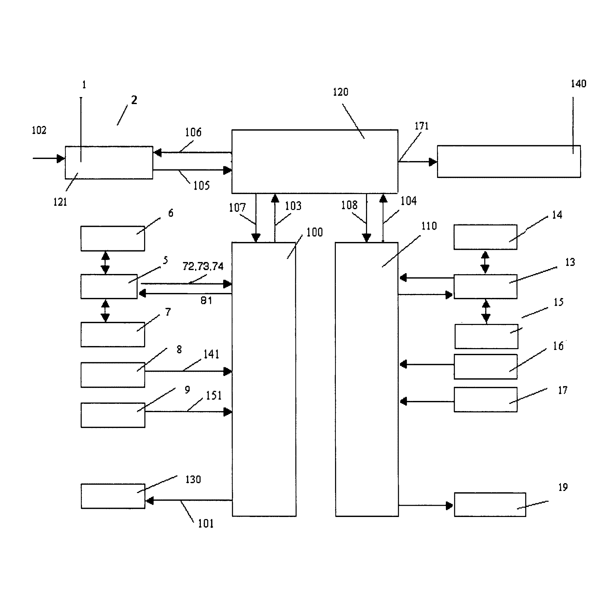
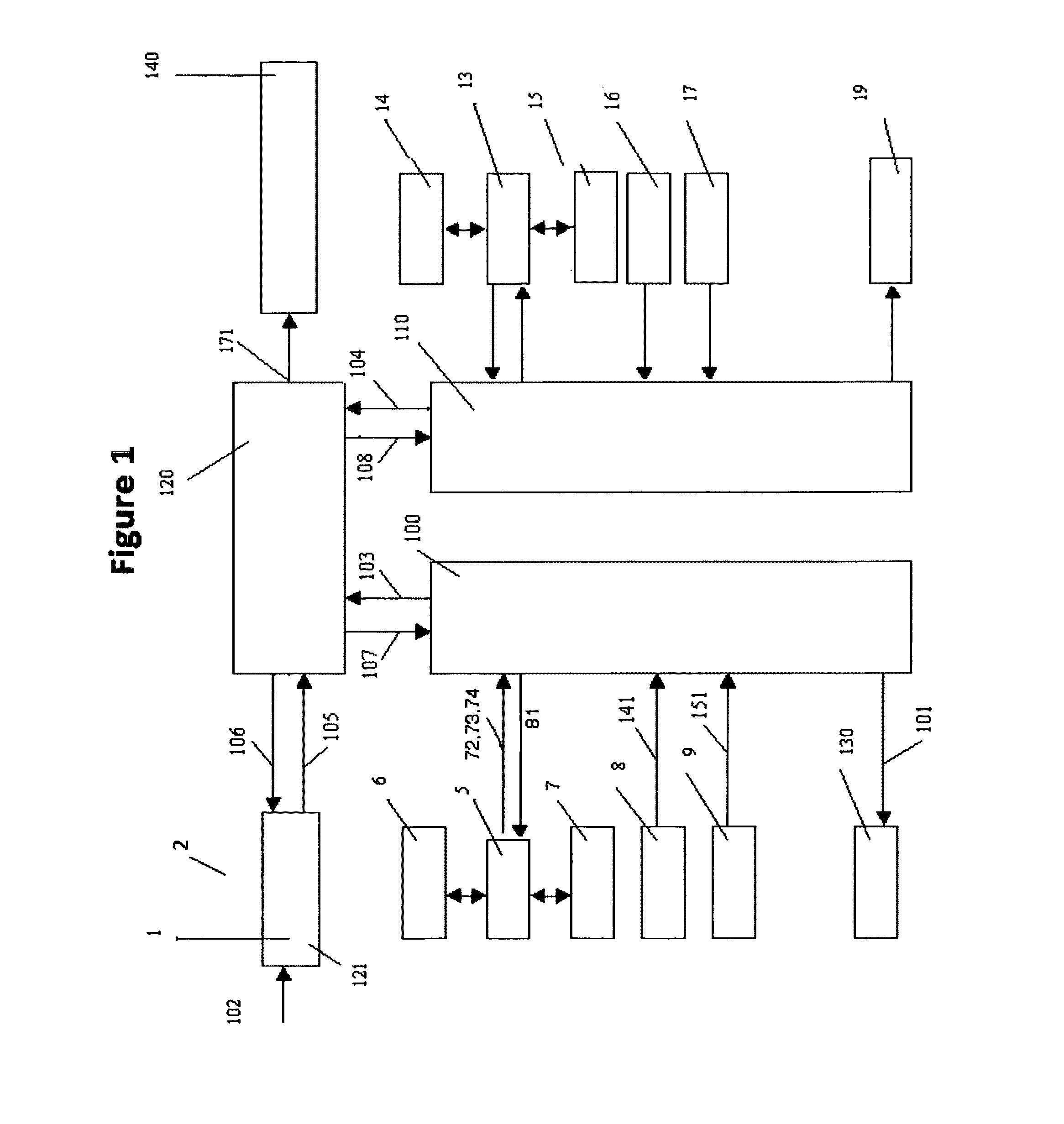
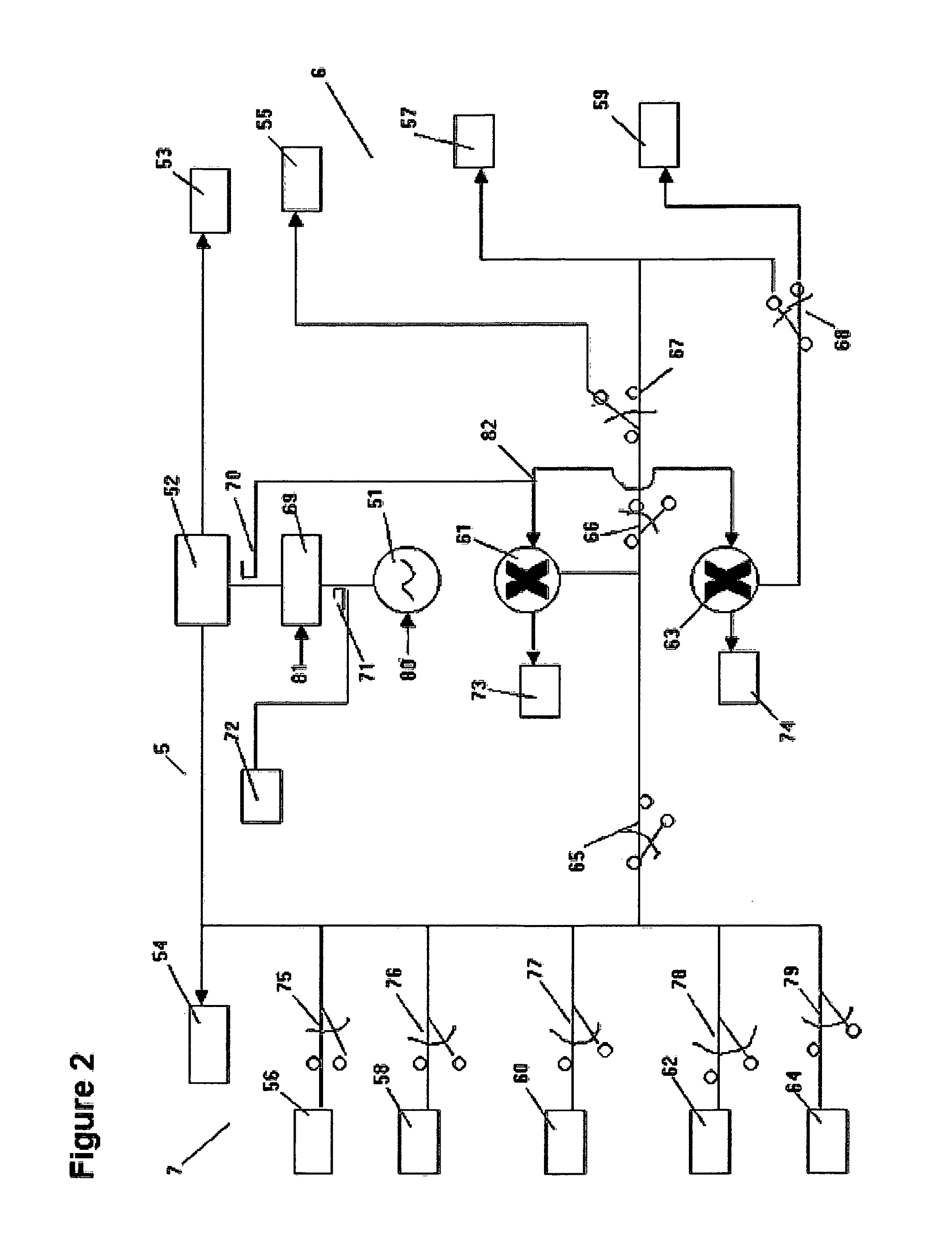
[0021]A block diagram of a triple function vehicle safety sensor system of this invention is shown generally in FIGS. 1-5 and designated (2). Elements of the system (2) include the following: a driver control module (1); a system processor (120); a driver-side processor (100); a driver-side radar transmitter / receiver assembly (5); a driver-side forward object detection radar antenna assembly (6); a driver-side side / rear object detection radar antenna assembly (7); a driver-side forward object detection video camera (8); a driver-side side / rear object detection video camera (9); a driver-side lane departure video camera (10); a driver-side object video display screen (130), a passenger-side processor (110); a passenger-side radar transmitter / receiver assembly (13); a passenger-side forward object detection radar antenna assembly (14); a passenger-side side / rear object detection radar antenna assembly (15); a passenger-side forward object detection video camera (16); a passenger-side ...


PUM


Abstract

A vehicle safety sensor system (VSSS) includes driver-side and passenger-side sensor means. The VSSS implements multiple safety functions as forward collision warning (or avoidance) and side / rear object detection. Subsystems of both sensor means are placed in the location normally occupied by side-view mirrors providing the driver an unobstructed view of both sensor means. The VSSS includes: (1) driver-side and passenger-side three-dimensional forward radar sensor; driver-side and passenger-side forward two dimensional video sensor; (2) driver-side and passenger-side side / rear two-dimensional radar sensor; driver-side and passenger-side side / rear two-dimensional video sensor; (3) data processor combining four outputs from the radar sensor and video sensor on driver-side and the passenger-side using data fusion for forward hazardous obstacle detection and validation; data processor also combining two outputs from the radar sensor and video sensor on driver side and passenger side using data fusion for side / rear hazardous obstacle detection and validation on respective sides of the vehicle.

Description

BACKGROUND OF THE INVENTION[0001]1. Field of the Invention[0002]This invention relates to detection of objects ahead of a highway vehicle, detection of objects in lanes adjacent to and immediately behind the vehicle, and to detection of boundaries of the lane occupied by the vehicle.[0003]2. Prior Art[0004]Heretofore currently available commercial vehicles sensor systems typically performed only a single function. On the other hand, radar object sensors capable of three dimensional (range, azimuth, and elevation) multiple object detection have been available for some time for military applications. Additionally, forward looking radar sensors have been deployed for automotive applications, primarily for adaptive cruise control systems. These systems are typically capable only of two dimensional (range and azimuth) detection. Two dimensional sensors are not adequately reliable for long distance determination of a hazard. Without elevation information of an object far ahead, it is diff...

Claims


Application Information

Patent Timeline
Patent Type & Authority Patents(United States)
IPC IPC(8): B60Q1/00
CPCB60Q9/008B60R1/00G01S7/03G01S7/032G01S13/4454G01S13/87G01S13/931G08G1/166H01Q1/3233G01S13/867B60R2300/105B60R2300/8046G01S2007/027G01S2013/936G01S2013/9385G01S2013/93274G01S2013/9316G01S7/027B60R1/23
Inventor KNOX, ROBERT M.
Owner EPSILON LAMBDA ELECTRONICS CORP
Learn More