

Wrap around self laminating wristband
a self-laminating, wristband technology, applied in the direction of identification means, instruments, people identification, etc., can solve the problem that the sides or the ends or even the sides and ends of the laminate overlay cannot be affixed in place, and achieve the effect of convenient die cutting
- Summary
- Abstract
- Description
- Claims
- Application Information
AI Technical Summary
Benefits of technology
Problems solved by technology
Method used
Image

Examples
Embodiment Construction
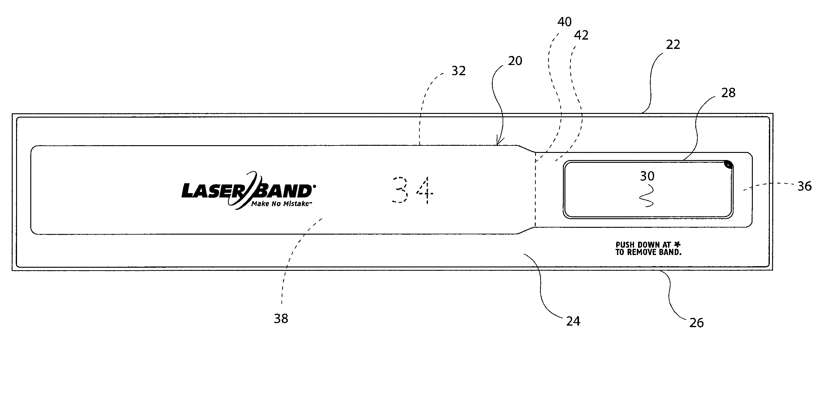
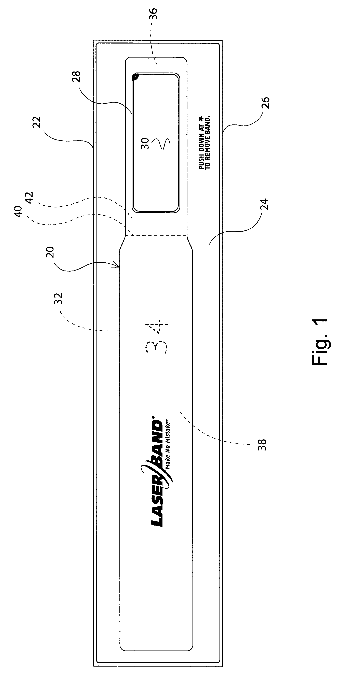
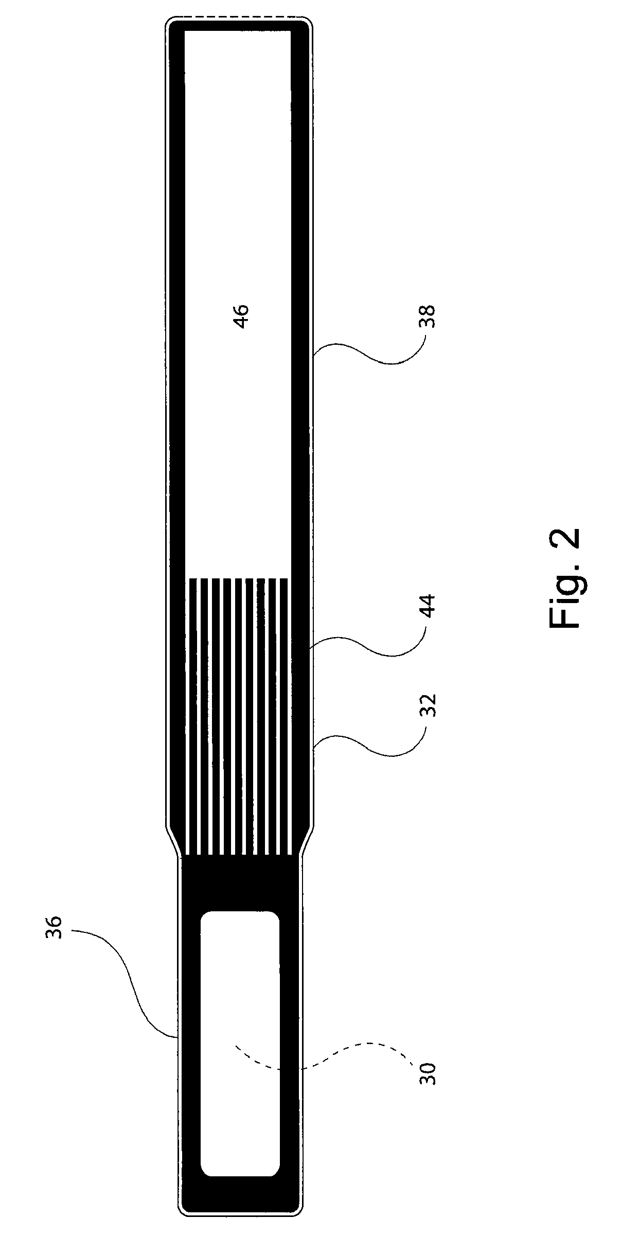
[0021]A first embodiment of the wraparound self laminating wristband 20 of the present invention is depicted in FIG. 1 and includes a two ply carrier 22 comprised of a top face ply 24 and a bottom laminate ply 26. A first die cut 28 in the face ply 24 forms an imaging area 30 and a second die cut 32 in the bottom laminate ply 26 forms a wristband strap 34. Die cut 32 may be an interrupted die cut, as depicted in other figures. The laminate wristband strap 34 is shown to preferably have a narrower end 36 whereat the imaging area 30 is adhered and a wider end 38. A dotted line 40 near the neck joining the narrower end 36 with the wider end 38 indicates the end of where a layer of adhesive 42 is applied to the narrower end 36 of wristband strap 34. A layer of release (not shown) surrounds the imaging area so that when the wristband 20 is separated from the carrier 22 it exposes the adhesive surrounding the imaging area 30. As there is preferably no release layer separating the laminate...
PUM
 Abstract
Description
Claims
Application Information