Torque sensor

a technology of torque sensor and sensor body, which is applied in the field of torque sensor, can solve the problems of insufficient robustness of the sensor, and achieve the effect of simple structur

Active Publication Date: 2012-02-07
LIEBHERR AEROSPACE LINDENBERG
View PDF22 Cites 7 Cited by
  • Summary
  • Abstract
  • Description
  • Claims
  • Application Information

AI Technical Summary

Benefits of technology

[0003]It is therefore the object of the present invention to provide a stable torque sensor of simple structur

Problems solved by technology

These sensors are, however, not robust enough for

Method used


Image

  • Torque sensor
  • Torque sensor
  • Torque sensor

Examples


Embodiment Construction

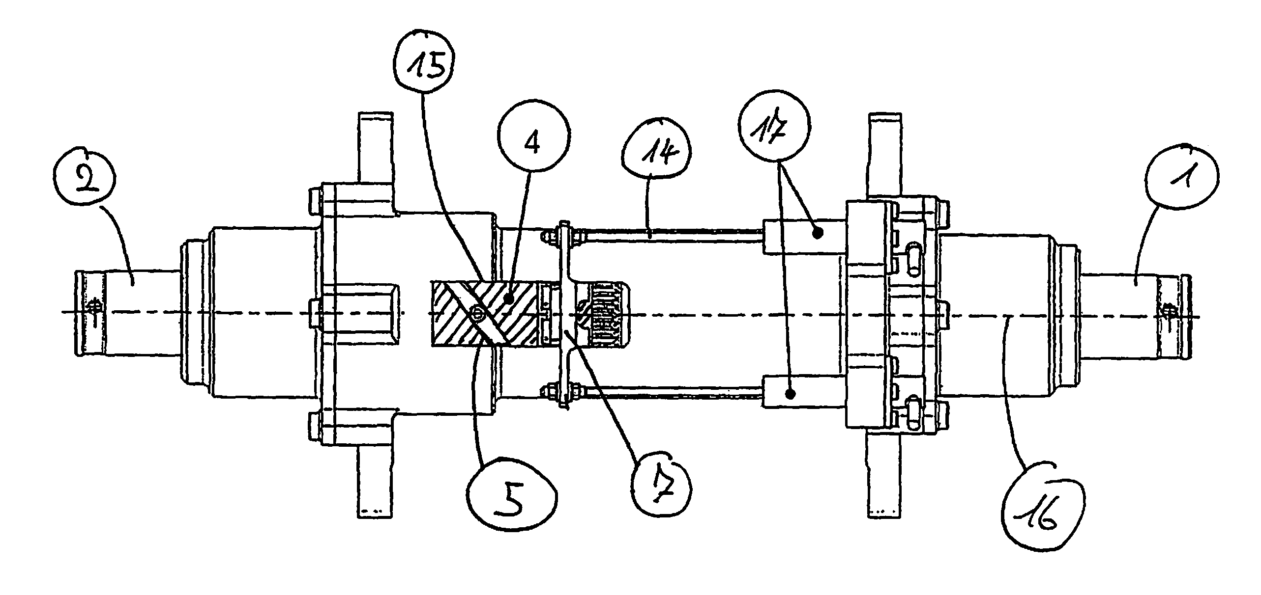
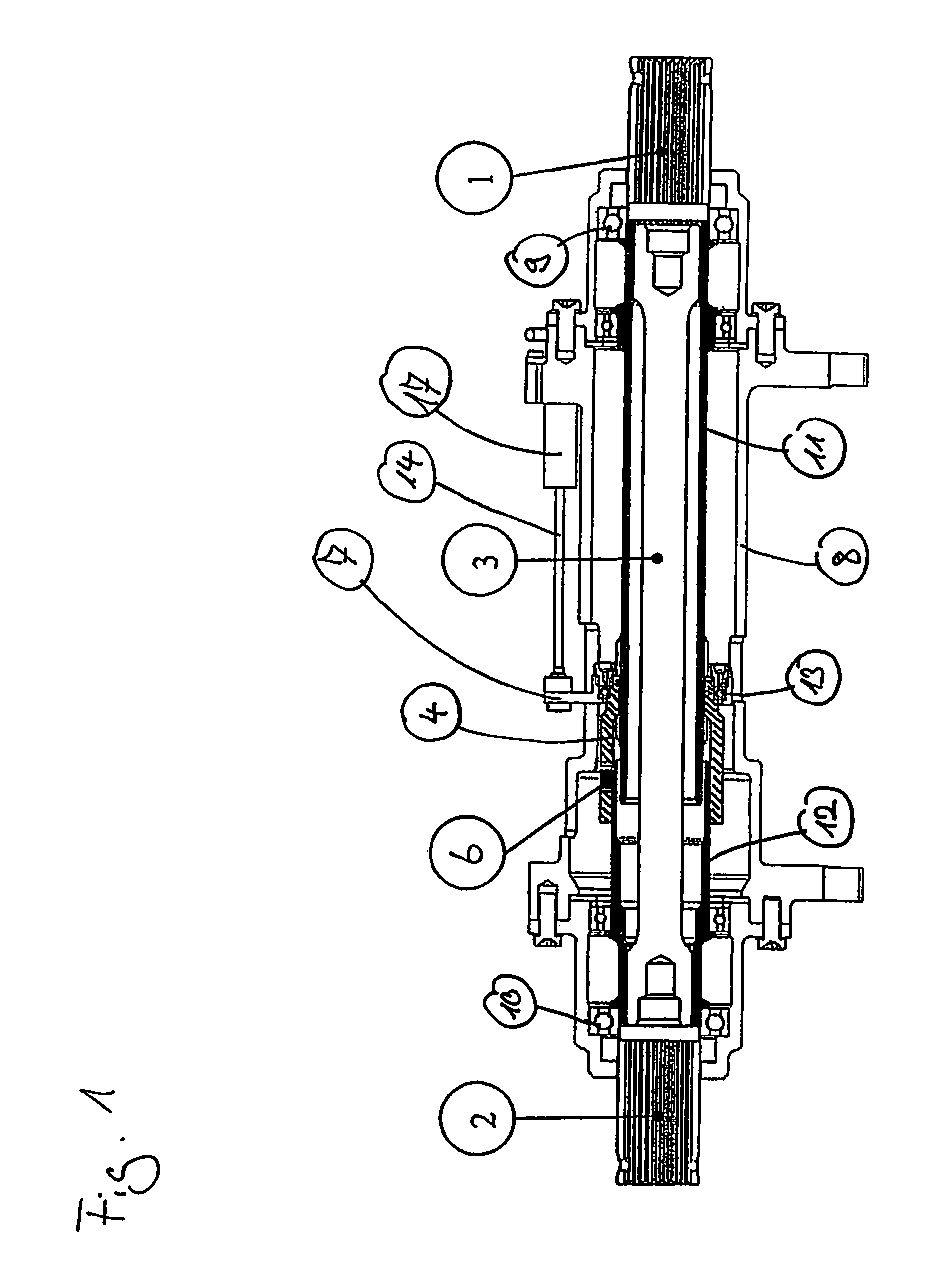
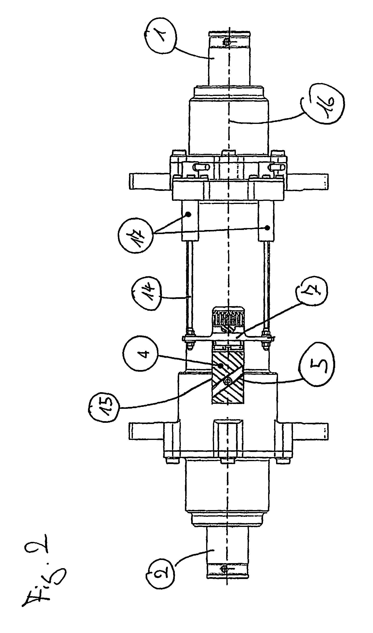
[0027]An embodiment of the torque sensor in accordance with the invention is now shown in FIGS. 1 and 2. Said torque sensor has a torsion spring 3 having a first side 1 and a second side 2, with the torsion spring 3 being rotated in itself by the torque transmitted by it so that the first side 1 rotates with respect to the second side 2 in the direction of rotation. In this respect, the torque sensor in accordance with the invention is advantageously used in a drive system, with it measuring the torque transmitted by a drive shaft of the drive system. For this purpose, the first side 1 and the second side 2 have connection regions to shaft sections of the drive system via which they can be connected in a torque-rigid manner to these shaft sections in the direction of rotation. The torsion spring 3 hereby transmits the rotation of the drive shaft and is in this respect rotated by an amount which depends on the transmitted torque.

[0028]The torque sensor in this respect has a housing 8...


PUM


Abstract

The present invention relates to a torque sensor comprising a torsion spring having first and second sides which are rotated with respect to one another by a torque applied to the torque sensor, wherein a mechanical coupling apparatus is provided between the first and second sides of the torsion spring and includes a movement element which is moved in the axial direction by a rotation of the first side with respect to the second side. In addition, a measuring apparatus is provided for the measurement of the axial movement of the movement element.

Description

BACKGROUND OF THE INVENTION[0001]The present invention relates to a torque sensor, in particular to a torque sensor for the detection of the torque in the shaft train of a drive system, in particular of a high lift system in an aircraft comprising a torsion spring having first and second sides which are rotated with respect to one another by a torque applied to the torque sensor. Such a torque sensor is, for example, integrated into the drivetrain of a drive system in that the first and second sides can be connected and / or are connected to corresponding drive shafts of the drivetrain.[0002]Previous torque sensors measure the torque using strain gages or piezostrictive sensors or magnetostrictive sensors are used. These sensors are, however, not robust enough for use over many years, in particular in aeronautics.SUMMARY OF THE INVENTION[0003]It is therefore the object of the present invention to provide a stable torque sensor of simple structure, in particular a torque sensor, which ...

Claims


Application Information

Patent Timeline
IPC IPC(8): G01L3/00
CPCG01L3/04G01L3/10
Inventor SCHMEISSER, KATYHAUZENBERGER, STEFANBASSETT, FRED
Owner LIEBHERR AEROSPACE LINDENBERG
Why Eureka
Try Eureka