Microdosing device

a microdosing device and microdosing technology, which is applied in the direction of valve operating means/releasing devices, combustion types, lighting and heating apparatus, etc., can solve the problems of evaporation of any liquid residue left behind, and achieve accurate and time-defined dosing, avoiding contamination of a new dosing quantity

Active Publication Date: 2012-02-14
APTAR RADOLFZELL
View PDF7 Cites 2 Cited by
  • Summary
  • Abstract
  • Description
  • Claims
  • Application Information

AI Technical Summary

Benefits of technology

[0013]This problem is solved in that the vibrating unit for a delivery time period for the discharge of the predetermined liquid quantity undergoes activation and then deactivation and that following the deactivation of the vibrating unit liquid residues which have been left behind in the dosing chamber are removed therefrom by a drying process. The method according to the invention is particularly suitable for the delivery of liquid in the form of atomized spray mist. As a result of the inventive solution a particularly accurate and time-defined dos...

Problems solved by technology

Thus, in the case of a suitable vibration frequency on the at least one boundary surface of the dosing c...

Method used


Image

  • Microdosing device
  • Microdosing device
  • Microdosing device

Examples


Embodiment Construction

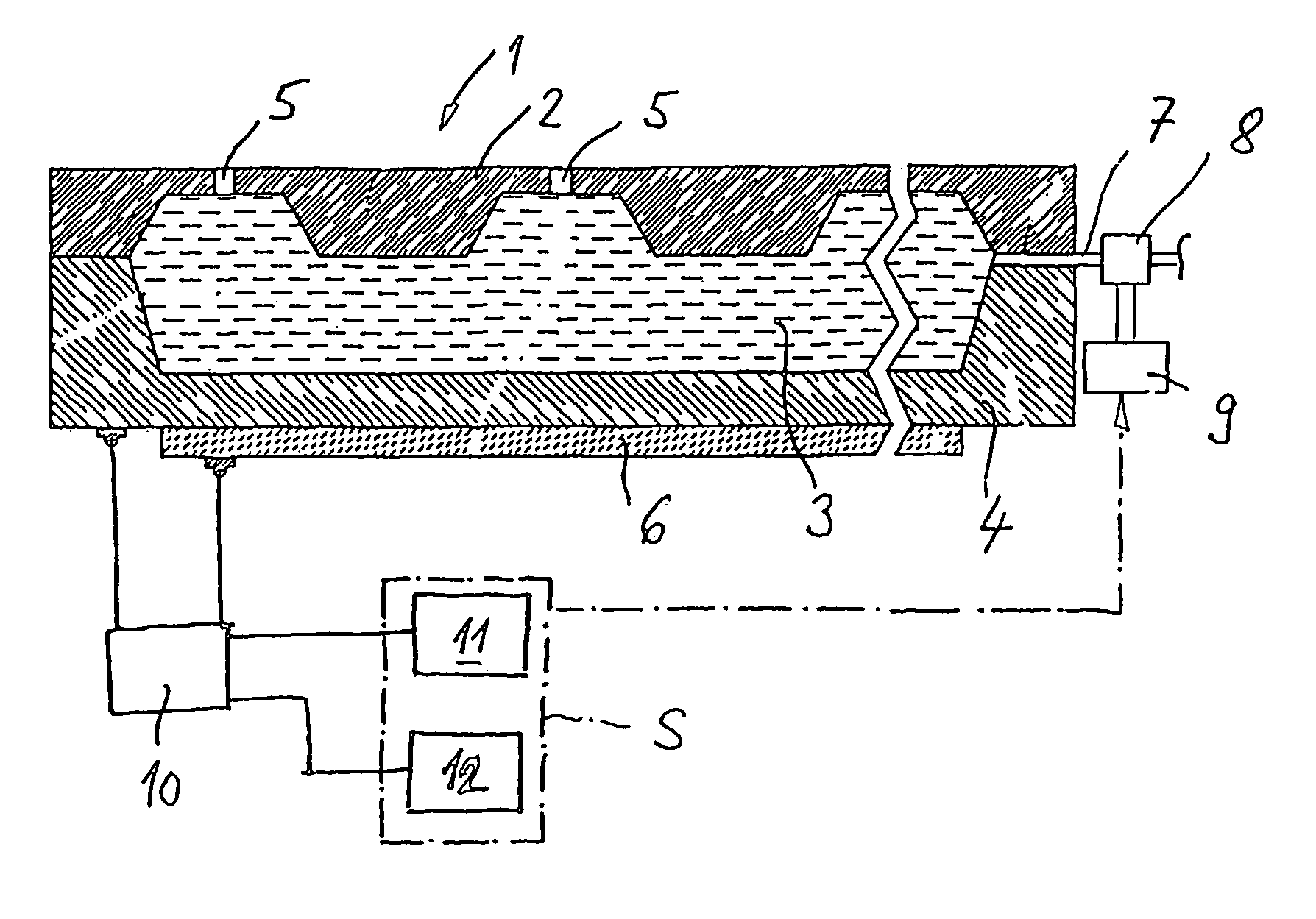
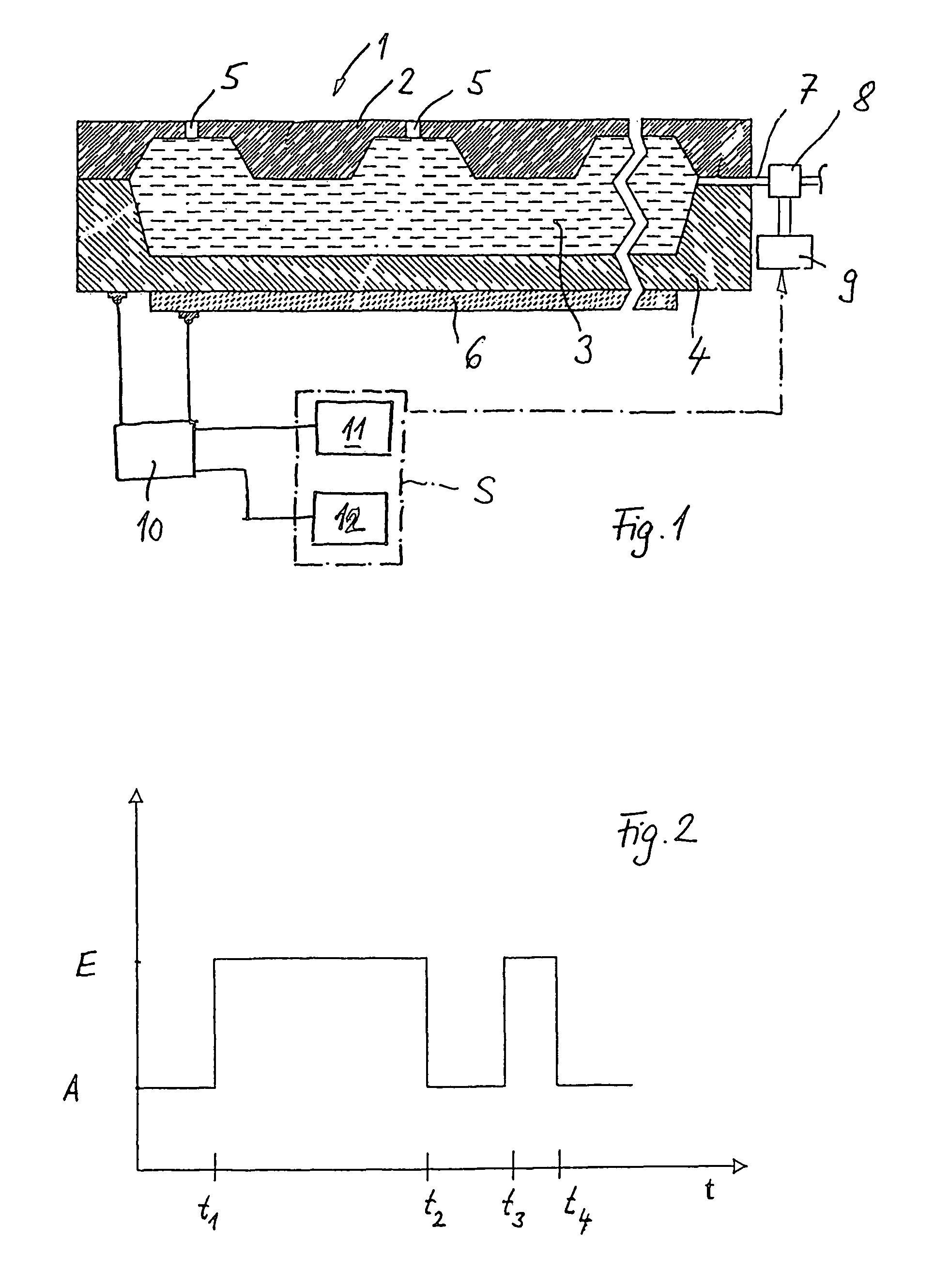
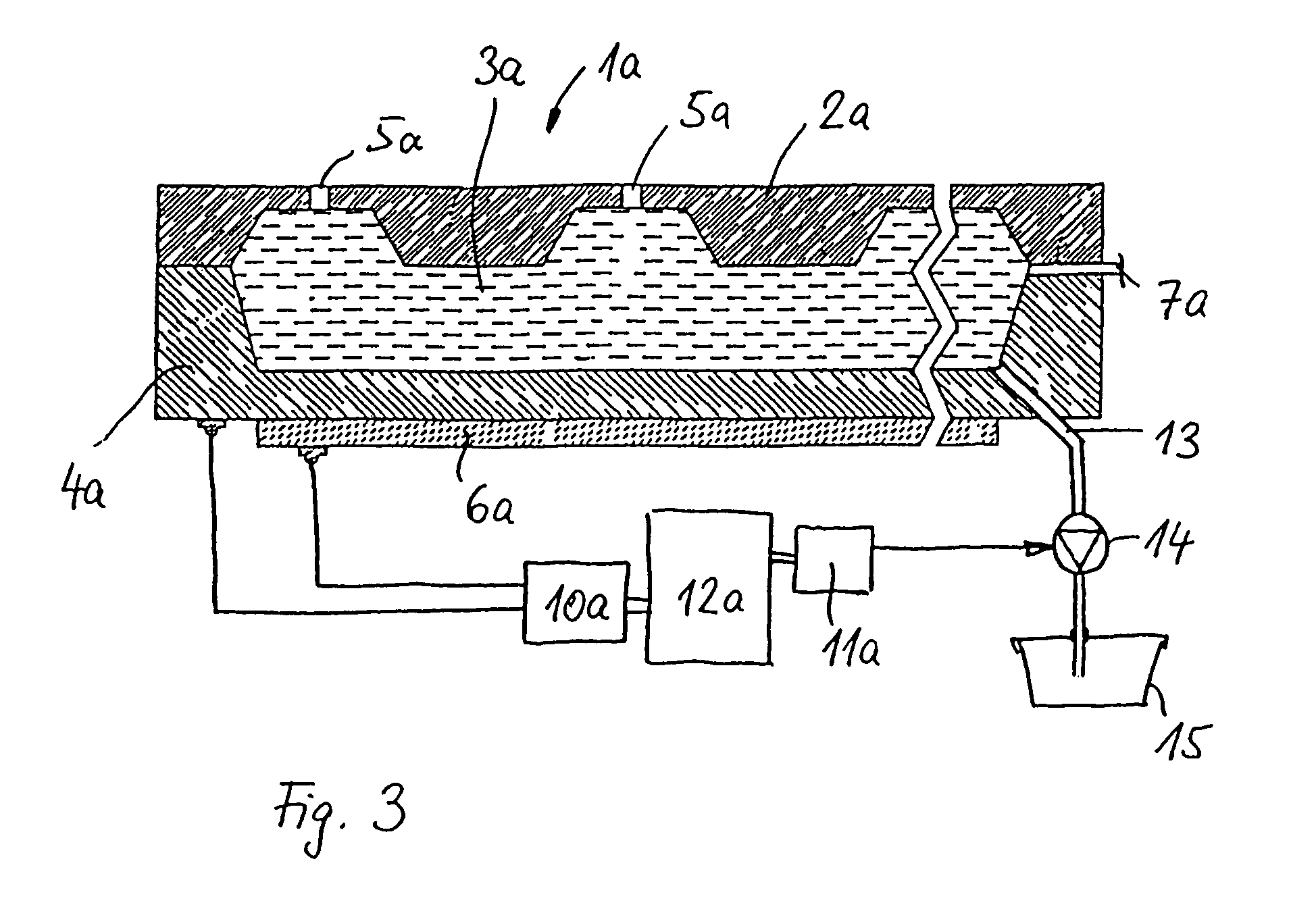
[0018]A microdosing device according to FIG. 1 is constructed as an atomizing unit and corresponds to the basic structure of the microdosing unit known from U.S. Pat. No. 6,196,219 B1. The atomizing unit 1 is part of a medical inhaler, in order to introduce via the respiratory tracts into the human body liquid pharmaceutical agents. However, the atomizing unit can also be used for other application purposes and in other application fields. For supplementary disclosure of the basic structure of the atomizing unit reference is made to the content of U.S. Pat. No. 6,196,219 B1.

[0019]The atomizing unit 1 has a dosing chamber 3, which is bounded at the top by a membrane 2 and at the bottom by a base structure 4. The base structure 4 is preferably made from glass, metal, ceramic, silicon, a piezoelectric crystal, a highly compressed polymer or the like. The membrane 2 for the dosing chamber 3 serving as a cover structure is preferably made from plastic, ceramic, metal, silicon or the like...


PUM


Abstract

A microdosing device with a dosing chamber for the at least temporary reception of a liquid quantity, and with which is associated at least one discharge opening is provided. A vibrating unit in operative connection with at least one boundary surface of the dosing chamber is provided in order to vibrate the same for a discharge process, and with a delivery function unit connected to the vibrating unit for activating the latter during a delivery time period. A drying function unit is additionally provided and can be activated in time-separated manner with respect to the delivery function unit in order to free the dosing chamber from liquid residues.

Description

FIELD OF THE INVENTION[0001]The invention relates to a microdosing device with a dosing chamber for the at least temporary reception of a liquid quantity and with which is associated at least one discharge opening, as well as with a vibrating unit, which is in operative connection with at least one boundary surface of the dosing chamber, in order to vibrate the same for a discharge process and with a delivery function unit connected to the vibrating unit for activating the latter during a delivery time period.BACKGROUND OF THE INVENTION[0002]Such a microdosing device is known from U.S. Pat. No. 6,196,219 B1. The known microdosing device has an atomizing unit in which is provided a dosing chamber for receiving a liquid quantity to be delivered. The dosing chamber is closed on one side by a membrane provided with several discharge openings in the form of perforations. With the facing boundary surface is associated a piezoelectric actuator serving as a vibrating unit. Into the dosing c...

Claims


Application Information

Patent Timeline
IPC IPC(8): A61M11/00F16K31/02F24J3/00A61M16/00A61M15/00B05B1/08B05B17/06B05C5/00
CPCA61M11/005B05B17/0638A61M15/0085
Inventor KOERNER, JOACHIMHELMLINGER, MICHAELSCHUERLE, HOLGERBOMMER, RENE
Owner APTAR RADOLFZELL
Why Eureka
Try Eureka