Image enhancement in the mosaic domain

a mosaic and image technology, applied in image enhancement, color signal processing circuits, instruments, etc., can solve the problems that the psf of the resulting optical system may still vary from the ideal, and achieve the effects of enhancing quality, reducing blur, and improving electronic images

Active Publication Date: 2012-02-14
DIGITALOPTICS CORPORATION
View PDF18 Cites 7 Cited by
  • Summary
  • Abstract
  • Description
  • Claims
  • Application Information

AI Technical Summary

Benefits of technology

[0009]Embodiments of the present invention provide methods and devices for processing and enhancement of electronic images, and particularly images that are produced by a mosaic image sensor. The sensor outputs a stream of pixel values belonging to a plurality of input sub-images, each of which is due to light of a different, respective color that is incident on the mosaic image sensor. An image restoration circuit filters the pixel values in each of the input sub-images so as to generate corresponding output sub-images with enhanced quality, such as with reduced blur. An image signal processor (ISP) then combines the output sub-images so as to generate a color video output image.
[0010]This arrangement has been found to give superior results when compared with conventional methods in which the mosaic sub-images are first combined to reconstruct a color output image before deblurring. Furthermore, in some embodiments, the output sub-images produced by the image restoration circuit are identical in format to the input sub-images produced by the mosaic image sensor, so that the image restoration circuit may be integrated with an existing sensor / ISP combination, between the sensor and the ISP, with little or no change to the sensor or ISP design.

Problems solved by technology

The PSF of the resulting optical system may still vary from the ideal due to focal variations and aberrations.

Method used


Image

  • Image enhancement in the mosaic domain
  • Image enhancement in the mosaic domain
  • Image enhancement in the mosaic domain

Examples


Embodiment Construction

Overview

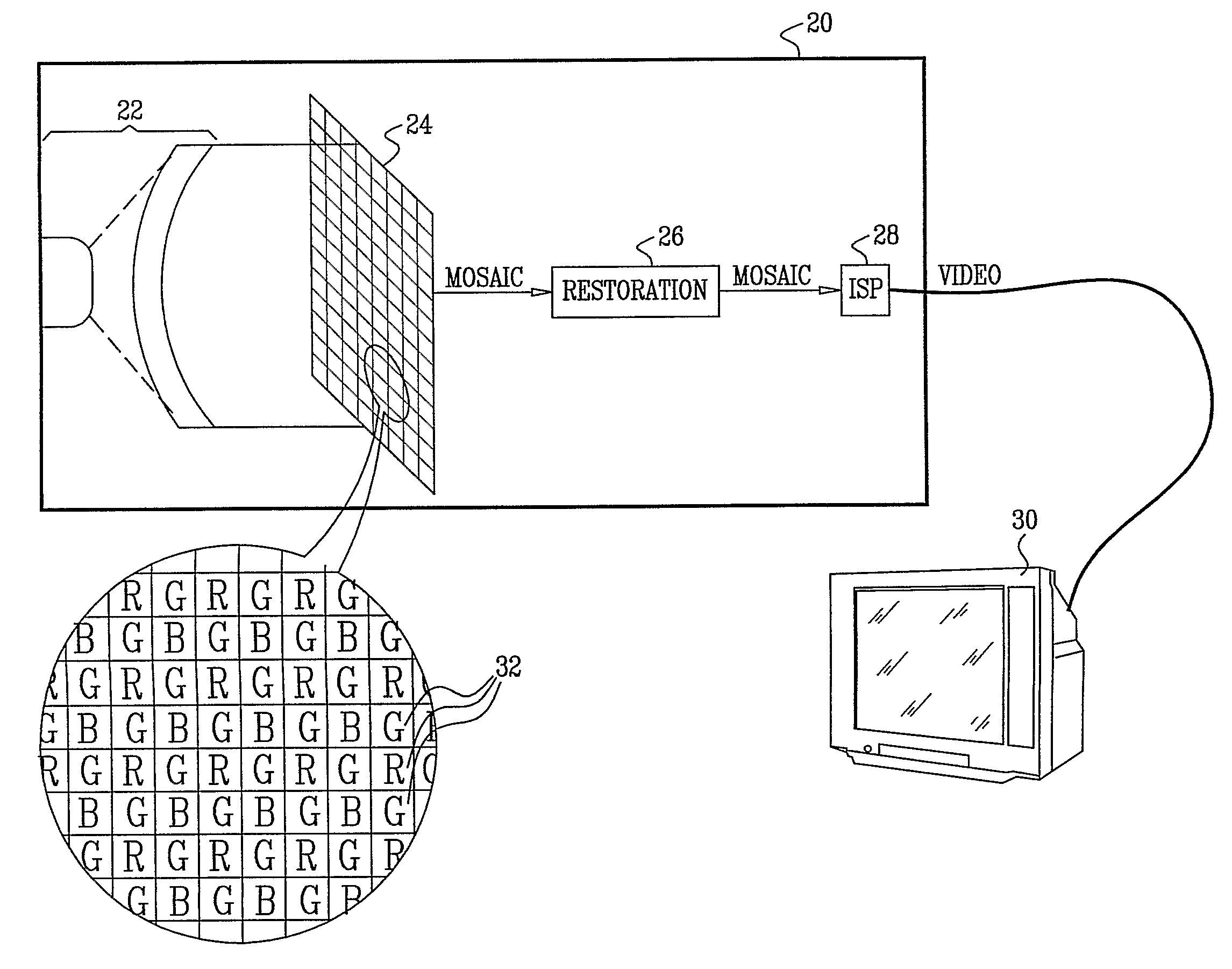
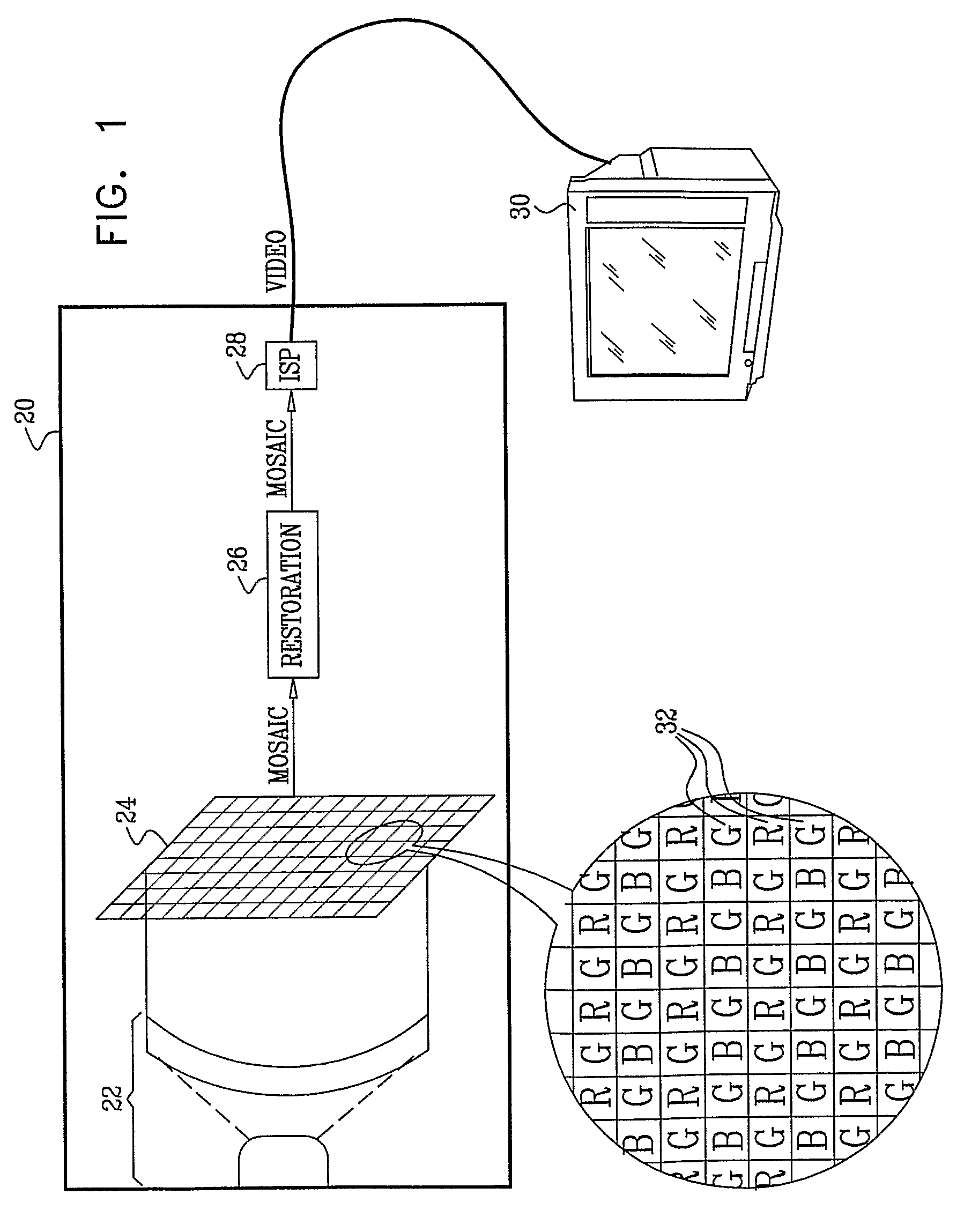
[0036]FIG. 1 is a block diagram that schematically illustrates an electronic imaging camera 20, in accordance with an embodiment of the present invention. This specific, simplified camera design is shown here by way of example, in order to clarify and concretize the principles of the present invention. These principles, however, are not limited to this design, but may rather be applied in reducing the blur in images in imaging systems of other types in which a sensor produces multiple sub-images of different colors, which are then combined to produce an enhanced color output image.

[0037]In camera 20, objective optics 22 focus light from a scene onto a mosaic image sensor 24. Any suitable type of image sensor, such as a CCD or CMOS image sensor, may be used in the camera. In this example, as well as in the description that follows, the sensor is assumed to have a Bayer-type mosaic filter, so that each pixel 32 in the image signal output by the sensor is responsive to either r...


PUM


Abstract

Imaging apparatus includes a mosaic image sensor (24), which is configured to generate a stream of input pixel values belonging to a plurality of input sub-images, each sub-image responsive to light of a different, respective color that is incident on the mosaic image sensor. An image restoration circuit (26) is coupled to receive and digitally filter the input pixel values in each of the input sub-images so as to generate a corresponding plurality of enhanced output sub-images. An image signal processor (ISP) (28) is coupled to receive and combine the plurality of the output sub-images in order to generate a color video output image.

Description

CROSS REFERENCE TO PRIOR APPLICATIONS[0001]This application is the U.S. national phase of International Application No. PCT / IL2006 / 001284 filed Nov. 7, 2006, which claims priority from U.S. Provisional Application No. 60 / 735,520, filed Nov. 10, 2005. The disclosures of both applications are incorporated herein by reference in their entirety. The International Application was published in English on May 18, 2007 as WO 2007 / 054931 under PCT Article 21(2).FIELD OF THE INVENTION[0002]The present invention relates generally to digital imaging, and specifically to methods and devices for enhancing image quality in digital cameras.BACKGROUND OF THE INVENTION[0003]The objective optics used in digital cameras are typically designed so as to minimize the optical point spread function (PSF) and maximize the modulation transfer function (MTF), subject to the limitations of size, cost, aperture size, and other factors imposed by the camera manufacturer. The PSF of the resulting optical system ma...

Claims


Application Information

Patent Timeline
Patent Type & Authority Patents(United States)
IPC IPC(8): H04N5/335H04N9/64G06K9/40H04N9/083
CPCG06T3/4015G06T7/0085H04N5/3572H04N5/3651G06T5/002G06T5/003G06T5/20H04N9/045G06T2207/20012G06T2207/20036G06T2207/20192H04N2209/046G06T2207/10024G06T7/13H04N25/671H04N23/843H04N25/134G06T7/00G06T7/40
Inventor LITVINOV, ANATOLYALON, ALEXALON, IRINAKIDRON, EINATKINROT, URI
Owner DIGITALOPTICS CORPORATION
Why Eureka
Try Eureka