Apparatus, method, and program for detecting three dimensional abdominal cavity regions

a three-dimensional image and abdominal cavity technology, applied in the field of three-dimensional image analysis process, can solve the problems of not necessarily the case that accurate measurement can be performed, the assumption of axial tomographic images in the vicinity of the pelvis fails, and the amount of errors to become great, so as to improve the accuracy of fat region discrimination, the effect of improving the extraction accuracy of the abdominal cavity region and improving the estimation accuracy of the curved surfa

Active Publication Date: 2012-02-14
FUJIFILM CORP
View PDF19 Cites 18 Cited by
  • Summary
  • Abstract
  • Description
  • Claims
  • Application Information

AI Technical Summary

Benefits of technology

[0043]Here, the estimated curved surfaces substantially contact the interiors of the plurality of bone boundary points that represent the boundaries between the bone regions and regions positions toward the interiors of the bone regions within the subject. Therefore, the curved surfaces are positioned toward the interior of the spinal column in the vicinity of the spinal column within the axial tomographic images. Accordingly, the regions Rgn3 between the outline of the abdominal cavity and the outer periphery of the abdominal wall muscle in the vicinity of the area behind the spinal column are outside the abdominal cavity region, and the extraction accuracy of the abdominal cavity region is improved. In the case visceral fat is measured, for example, the regions Rgn3 are removed from the visceral fat regions, and therefore, the accuracy of fat region discrimination is improved.
[0044]In addition, the plurality of bone boundary points within the plurality of axial tomographic images are utilized three dimensionally to estimate the curved surfaces to extract the three dimensional abdominal cavity region. Therefore, the estimation accuracy of the curved surfaces is higher compared to the method disclosed in Patent Document 3, in which the regions are discriminated independently for each axial tomographic image, because data regarding the bone boundary points in the axial direction of the body are also utilized. As a result, the accuracy of abdominal cavity region extraction is also improved.
[0045]A configuration may be adopted, in which the diaphragm portion of the subject is extracted, and a region within the three dimensional image surrounded by the extracted diaphragm portion and the curved surfaces is extracted as the three dimensional abdominal cavity region. In this case, the extraction accuracy with respect to the upper edge portion of the abdominal cavity is improved.
[0046]Configurations may be adopted, in which the outline of the surface of the subject's body or the outline of the exterior of the abdominal wall muscles are extracted, and the curved surfaces are estimated such that they do not extend outside the extracted outlines. In these cases, the curved surfaces being estimated as shapes that protrude outside of these outlines in portions of the subject in the vicinity of the abdomen where no ribs or pelvis are present can be avoided. Therefore, the accuracy of estimation of the curved surfaces in the vicinity of the abdomen is improved. As a result, accuracy of abdominal cavity region extraction is improved in the vicinity of the abdomen.
[0047]In addition, a configuration may be adopted, wherein: reference lines having endpoints at both sides of a line that bisects the subject in the horizontal direction are set at positions which are clearly anatomically in the abdominal cavity region within each of the plurality of axial tomographic images, such that the distances between the end points become shorter in axial tomographic images that represent lower portions of the subject, searches are performed along a plurality of lines of sight that do not intersect and extend from a plurality of points along the search reference lines toward the exterior of the subject, and points that contact the bone regions first are detected as the bone boundary points. In this case, the initiation points of the searches include those which are shifted from the center of the subject in the horizontal direction. Therefore, it becomes possible to set the bone boundary points along the interiors of the spinal column (vertebrae) positioned at the center. In addition, the search reference lines are set such that the distances between the end points become shorter in axial tomographic images that represent lower portions of the subject. Therefore, the search initiation points can be set within the interior of the pelvis in axial tomographic images in the vicinity of the pelvis. This enables setting of the bone boundary points within the interior of the pelvis, which contributes to improvements in the accuracy of estimation of the curved surfaces.

Problems solved by technology

Therefore, if the volume of body fat is measured three dimensionally by calculating the sum of measurement results obtained from a plurality of axial tomographic images of the abdominal region, the erroneous judgments will cause the amount of errors to become great.
Therefore, it is not necessarily the case that accurate measurement can be performed.
Therefore, although a certain degree of accuracy in definition can be expected in axial tomographic images in the vicinity of the spleen, the assumption fails in axial tomographic images in the vicinity of the pelvis.
Accordingly, the boundaries between subcutaneous fat and visceral fat cannot be accurately defined in these images.

Method used


Image

  • Apparatus, method, and program for detecting three dimensional abdominal cavity regions
  • Apparatus, method, and program for detecting three dimensional abdominal cavity regions
  • Apparatus, method, and program for detecting three dimensional abdominal cavity regions

Examples


Embodiment Construction

[0071]Hereinafter, a three dimensional body fat measuring system in which a three dimensional abdominal cavity region extracting apparatus of an embodiment of the present invention is incorporated will be described with reference to the attached drawings.

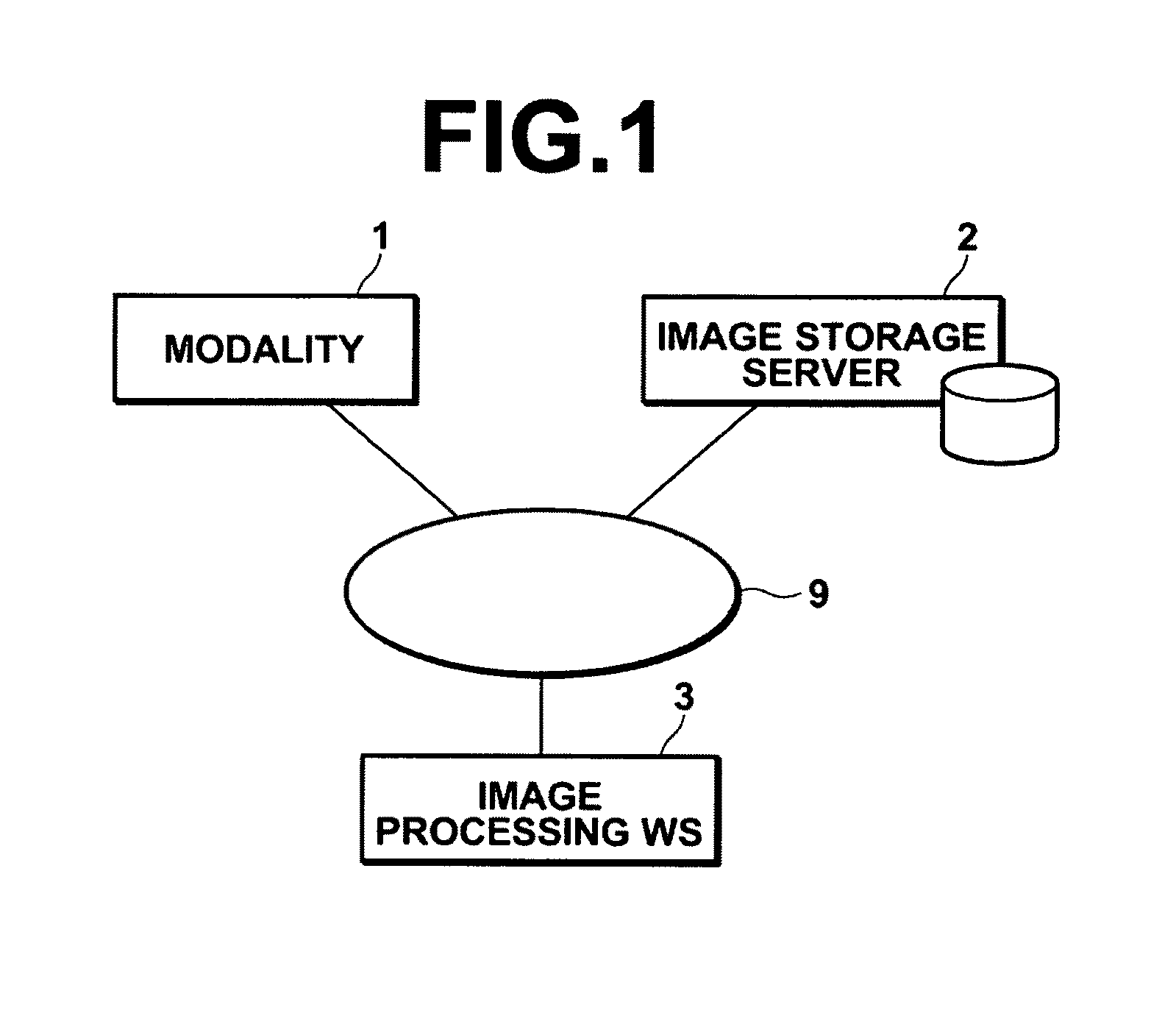
[0072]FIG. 1 is a diagram that illustrates the hardware structure of a medical image information display apparatus according to a first embodiment of the present invention. As illustrated in FIG. 1, the system includes: a modality 1; an image storage server 2; and an image processing workstation 3. The modality 1, the image storage server 2, and the image processing workstation 3 are connected via a network 9 such that they can communicate with each other.

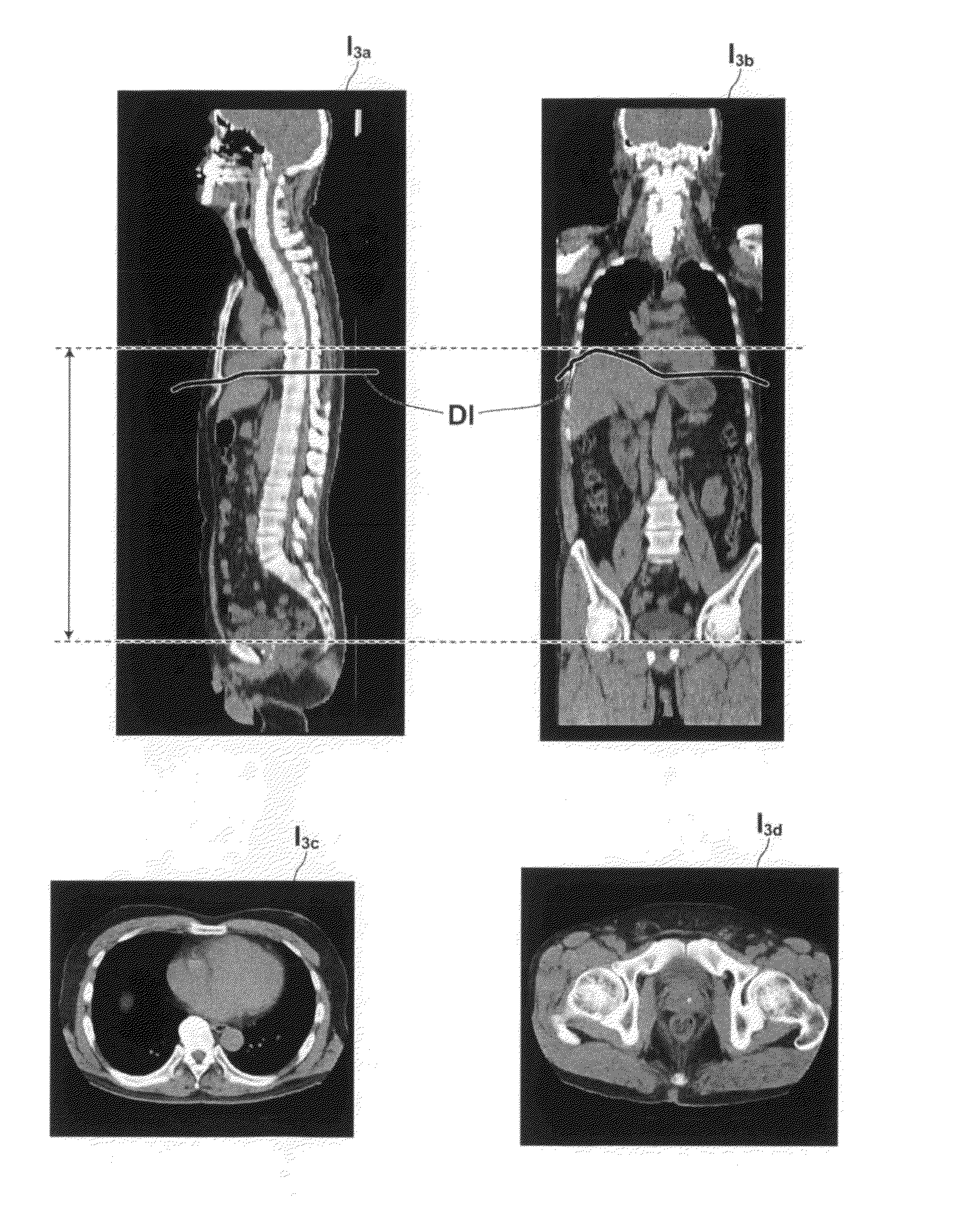
[0073]The modality 1 obtains three dimensional medical images (voxel data) V that represent subjects. Specifically, the modality 1 is a CT apparatus, an MRI apparatus, an ultrasound apparatus, or the like. In the present embodiment, the three dimensional images V are constituted by...


PUM


Abstract

An apparatus is provided with: a bone region extracting section for extracting bone regions representing bones of a subject within a plurality of axial tomographic images obtained from a three dimensional image representing a portion of the subject from the vicinity of the upper end of the liver to the vicinity of the pubic symphysis; a bone boundary point detecting section for detecting a plurality of bone boundary points representing the boundaries between the detected bone regions and regions positioned toward the interiors of the bone regions within the plurality of axial tomographic images; and an abdominal cavity region extracting section for estimating curved surfaces within the three dimensional image that substantially contact the interiors of the plurality of bone boundary points detected in each of the plurality of axial tomographic images, and for extracting a region surrounded by the curved surfaces as a three dimensional abdominal cavity region.

Description

CROSS-REFERENCE TO RELATED APPLICATIONS[0001]The present invention is a 35 USC 371 national stage entry of PCT / JP2009 / 000718, filed Feb. 19, 2009, which claims priority from Japanese Patent Application No. 2008-097630, filed Apr. 3, 2008, the contents of all of which are herein incorporated by reference in their entirety.BACKGROUND OF THE INVENTION[0002]1. Field of the Invention[0003]The present invention is related to a three dimensional image analyzing process. Particularly, the present invention is related to an apparatus and a method for performing a process to detect abdominal cavity regions of subjects within three dimensional images, and to a program that causes a computer to execute the method.[0004]2. Description of the Related Art[0005]Amounts of body fat and body fat percentages are measured by detecting regions corresponding to CT values that represent fat within cross sectional images perpendicular to the axes of the bodies of subjects (axial cross sections) in the vici...

Claims


Application Information

Patent Timeline
Patent Type & Authority Patents(United States)
IPC IPC(8): G06K9/00
CPCA61B5/1075A61B5/416A61B5/4872A61B6/466G06T7/0083A61B5/055A61B5/4504A61B6/032A61B8/0858G06T2207/10081G06T2207/30008G06T7/12
Inventor MASUMOTO, JUN
Owner FUJIFILM CORP
Why Eureka
Try Eureka