Multiaxial acceleration sensor and angular velocity sensor

a multi-axial acceleration and sensor technology, applied in the direction of acceleration measurement using interia forces, turn-sensitive devices, instruments, etc., can solve the problems of high temperature dependence, detection value contains errors, and piezoelectric constant of pzt is highly dependent on temperatur

Inactive Publication Date: 2012-02-21
KK TOSHIBA
View PDF9 Cites 32 Cited by
  • Summary
  • Abstract
  • Description
  • Claims
  • Application Information

AI Technical Summary

Problems solved by technology

However, in the sensor having the aforementioned piezoresistive device, its detection value contains an error if the temperature of ambient environment is changed, because the piezoresistive has temperature dependency.
Particularly in the case where the sensor is used in automobile industry, there occurs such a problem that the temperature compensation is required in a wide operating temperature range of −40° C. to 120° C.
However, piezoelectric zirconate titanate (PZT) needs to be used as a piezoelectric device, thereby posing a problem that the piezoelectric constant of the PZT is highly dependent on the temperature.
The multi-axial accelerometer and angular rate sensor of prior art have problems that their temperature dependency is high or they are difficult to manufacture.

Method used


Image

  • Multiaxial acceleration sensor and angular velocity sensor
  • Multiaxial acceleration sensor and angular velocity sensor
  • Multiaxial acceleration sensor and angular velocity sensor

Examples


first embodiment

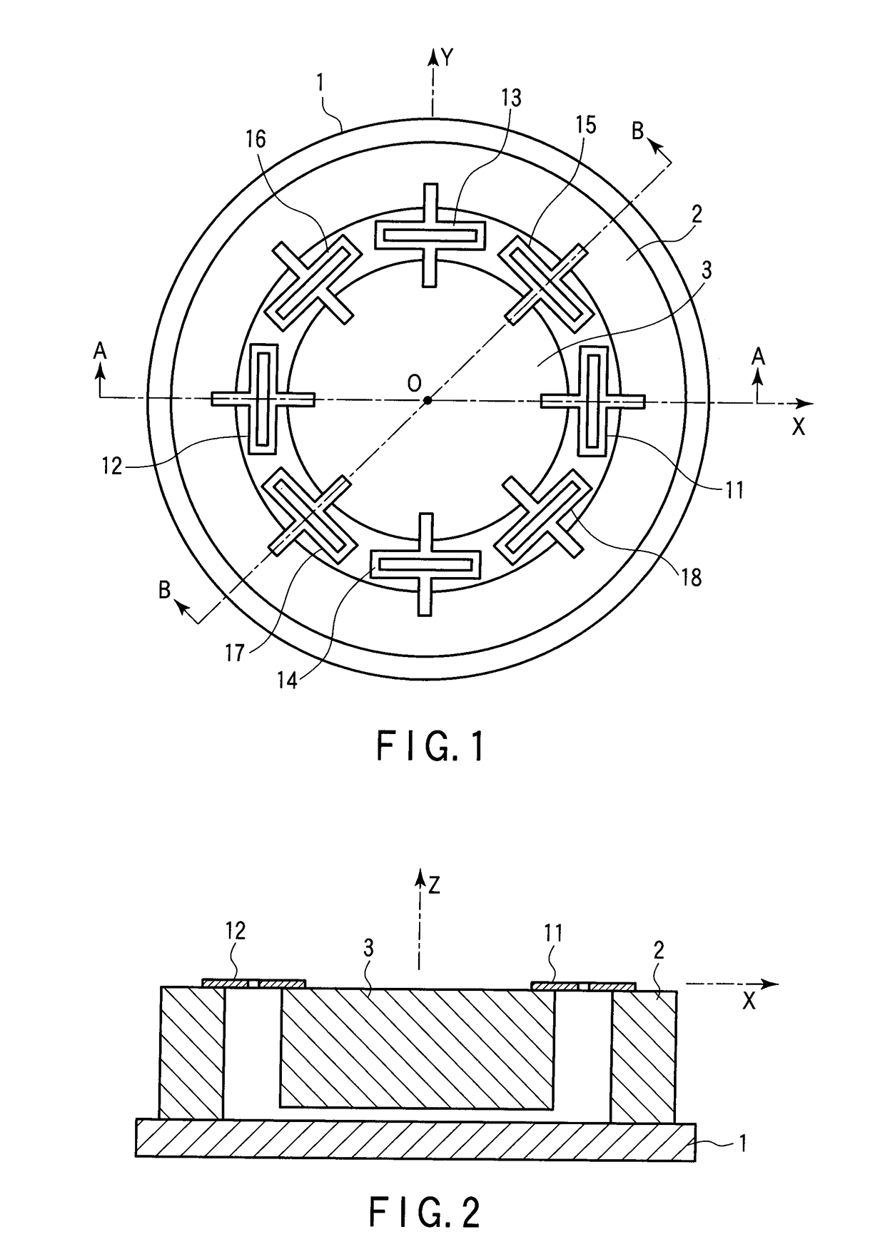
[0077]FIG. 1 is a top view showing schematically the accelerometer of this embodiment and FIG. 2 is a sectional view taken along the line A-A of FIG. 1.

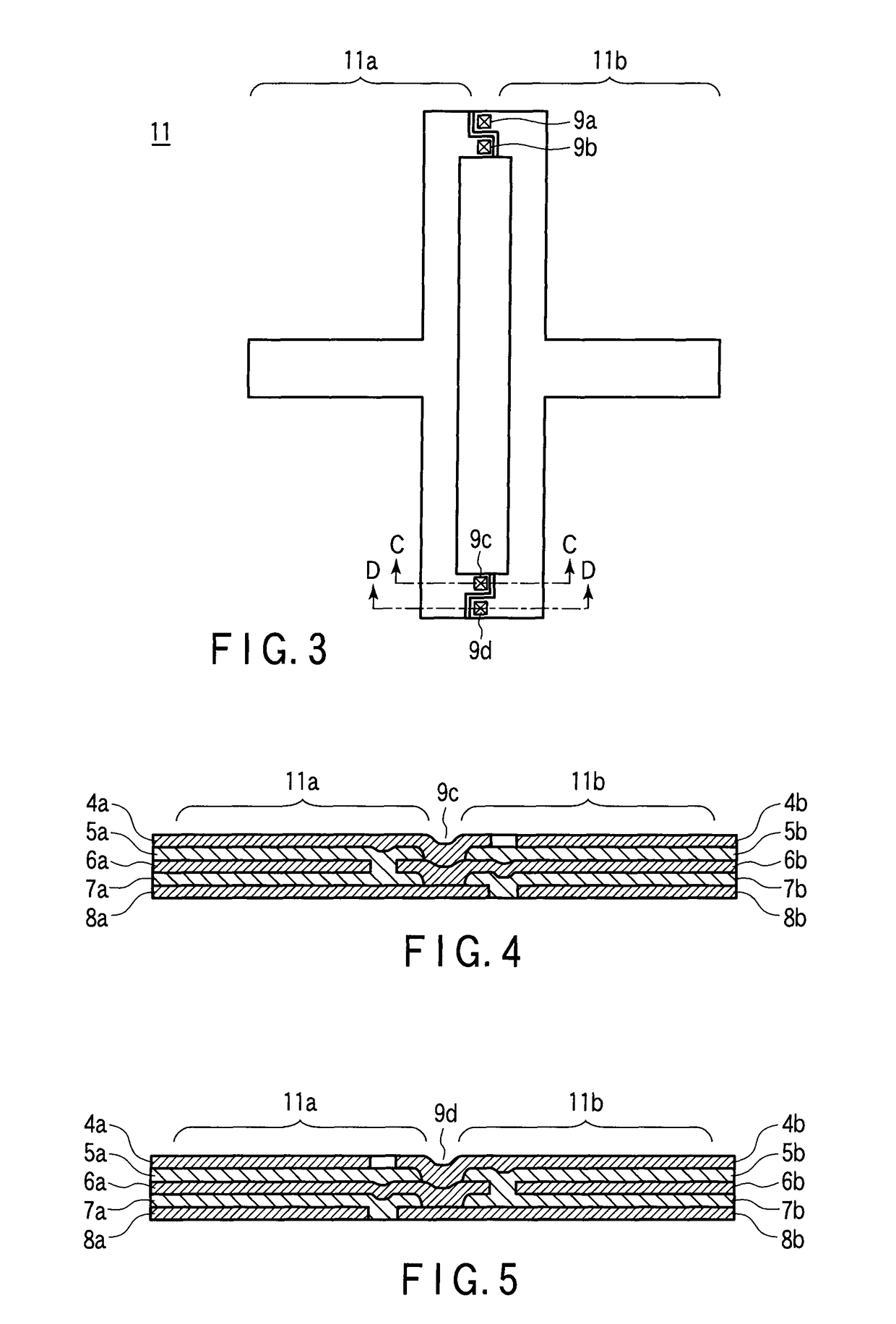
[0078]The accelerometer includes a disc-like base plate 1, a supporting ring-like or frame-like base 2 which is provided and fixed to the top face of the base plate 1, having a supporting surface and in which a hollow portion is formed internally, a disc-like weight 3 disposed in the central area of the base plate 1 within the ring-like base 2, and eight (first to fourth pairs of) piezoelectric bimorph detectors 11 to 18, each end of which is connected to the supporting surface of the base 2 while the other end is connected to the weight 3 so that each thereof is flexed. The piezoelectric bimorph detectors 11 to 18 of the first to fourth pairs have an identical size and shape as shown in FIG. 1.

[0079]In this specification, considering convenience for description, a home position O is set in the center of the top surface of the weight...

second embodiment

[0119]The basic principle of the angular rate sensor will be described prior to a detailed description of the angular rate sensor according to the second embodiment of the present invention.

[0120]The angular rate sensor of the present invention detects an angular rate using the Coriolis force acting on the weight 3. The basic principle of detecting the angular rate by detecting the Coriolis force will be described with reference to FIG. 21. Now assume that an oscillator 10 is placed at the home position of a XYZ three-dimensional coordinate system. This oscillator 10 corresponds to the weight 3 in the sensor of the present invention. To detect the angular rate ωx around the X-axis of this oscillator 10, a vibration Uz in the Z-axis direction is applied to this oscillator 10 as shown in FIG. 21 and then, a Coriolis force Fcy generated in the Y-axis direction is measured. The Coriolis force Fcy generated in the oscillator 10 is expressed in the following expression:

Fcy=2m·vz·ωx

where ...

third embodiment

[0155]In the third embodiment, an angular rate sensor capable of simultaneously detecting triaxial accelerations and biaxial angular velocities will be described in detail. The angular rate sensor of the third embodiment has the same structure as the angular rate sensor of the second embodiment shown in FIG. 22. The combination of the exciter and the detector and part of the detection circuit are partly modified.

[0156]In this angular rate sensor, the piezoelectric bimorph devices 31 to 34 are used as detection devices for detecting a displacement in the X-axis direction of the weight 3 and the piezoelectric bimorph devices 35 to 38 are used as detection devices for detecting a displacement in the Y-axis direction of the weight 3 as in the second embodiment. The piezoelectric bimorph devices 41 to 44 are used as detection devices for detecting a displacement in the Z-axis direction of the weight 3 and the piezoelectric bimorph devices 45 to 48 are used as excitation devices for vibra...


PUM


Abstract

In a angular rate sensor, a weight and a base are connected directly through piezoelectric bimorph detectors and piezoelectric bimorph exciters each having a bent portion. When acceleration is applied to the weight, the weight is displaced so as to deform the piezoelectric bimorph detectors. Due to this deformation, charges generated in the piezoelectric bimorph detectors are detected so as to detect acceleration. If an angular rate is applied to the weight when the weight is vibrated by the piezoelectric bimorph exciters, Coriolis force is generated in the weight so as to deform the piezoelectric bimorph detectors. Due to this deformation, charges generated in the piezoelectric bimorph detectors are detected so as to detect the angular rate.

Description

CROSS-REFERENCE TO RELATED APPLICATIONS[0001]This application is based upon and claims the benefit of priority from prior Japanese Patent Application No. 2008-239448, filed Sep. 18, 2008, the entire contents of which are incorporated herein by reference.BACKGROUND OF THE INVENTION[0002]1. Field of the Invention[0003]The present invention relates to a sensor capable of detecting three-axis accelerations and an angular rate around two axes using a piezoelectric device.[0004]2. Description of the Related Art[0005]In electronic industry, automobile industry and machine industry, demands for the multi-axial accelerometer and angular rate sensor having a small size and a high reliability have been increased. Such sensors are requested to be capable of detecting the acceleration and angular rate of each component of two dimensions or three dimensions.[0006]The multi-axial accelerometer has a weight as disclosed in Japanese Patent 3141954 and this weight is held by a flexible base plate aro...

Claims


Application Information

Patent Timeline
Patent Type & Authority Patents(United States)
IPC IPC(8): G01P15/09G01C19/56G01P15/18
CPCG01C19/56G01P15/0922G01P15/14G01P15/18G01P2015/084
Inventor KAWAKUBO, TAKASHINAGANO, TOSHIHIKONISHIGAKI, MICHIHIKO
Owner KK TOSHIBA
Why Eureka
Try Eureka