Photovoltaic soundproof wall

a photovoltaic and soundproof wall technology, applied in the field of soundproof walls, can solve the problems of reducing the generation efficiency of solar cells, unable to meet the needs of vehicles, and the formation of relatively thick panels cannot allow the outside appearance of the road to be seen by the occupants of vehicles, so as to reduce the emission of co2, reduce the noise of road traffic, and facilitate the production of electricity

Inactive Publication Date: 2012-02-21
PARK JAE SUNG
View PDF21 Cites 2 Cited by
  • Summary
  • Abstract
  • Description
  • Claims
  • Application Information

AI Technical Summary

Benefits of technology

[0012]Accordingly, the present invention has been made in view of the above-mentioned problems occurring in the prior art, and it is an object of the present invention to provide a photovoltaic soundproof wall that is configured to have a device for receiving solar energy to generate electricity therefrom mounted at the inside thereof, thereby sensing the quantity of electricity generated to permit solar cells to be positioned to an optimal generation state, whereby the reduction of road traffic noises and the easy production of electricity can be achieved, and with the development of new recycling energy, the reduction of the emission quantity of CO2 can be achieved.
[0013]It is another object of the present invention to provide a photovoltaic soundproof wall that is capable of sensing an azimuth angle in a front direction of solar cells to allow angles of slats to which the solar cells are attached to be easily adjusted to an optimal state at a given time.

Problems solved by technology

Conventional soundproof walls, for example, are formed of relatively thick panels capable of efficiently reducing road traffic noises therefrom, but the formation of the relatively thick panels fails to allow the outside appearance of the road to be seen by the occupants of the vehicle.
In this case, the outside appearance from the road is seen easily by the excellent clarity of the soundproof members, but since the thicknesses of the soundproof members are substantially low, the conventional soundproof walls do not provide high soundproof effects.
As a result, the generation efficiencies of the solar cells are decreased by the dust generated from the road, and further, the solar cells exposed to the outside are rapidly eroded and damaged.
According to the conventional arts, additionally, a unit for tracking solar positions is mounted on the photovoltaic generation device so as to increase the generation efficiencies of the solar cells, but the entire configuration becomes very complicated by the addition of the unit for tracking the solar positions.
Moreover, existing solar cell modules cannot be installed in vertical spaces, and because of the limitation of the installation area of the soundproof walls, the existing solar cell modules are very dangerous, in view of their shape, in their installation.

Method used


Image

  • Photovoltaic soundproof wall
  • Photovoltaic soundproof wall
  • Photovoltaic soundproof wall

Examples


Embodiment Construction

[0025]Hereinafter, an explanation on a photovoltaic soundproof wall according to the present invention will be in detail given with reference to the attached drawings.

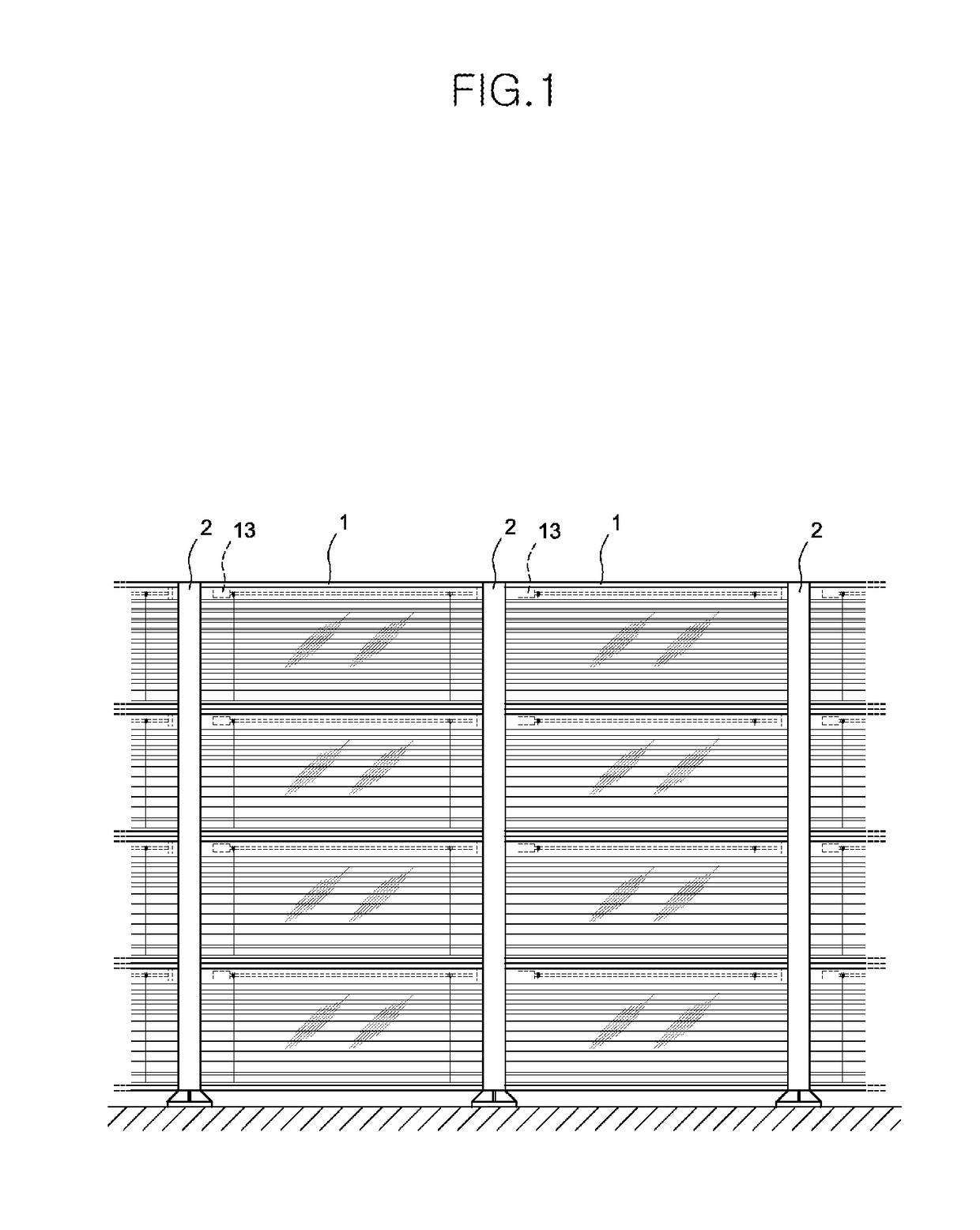
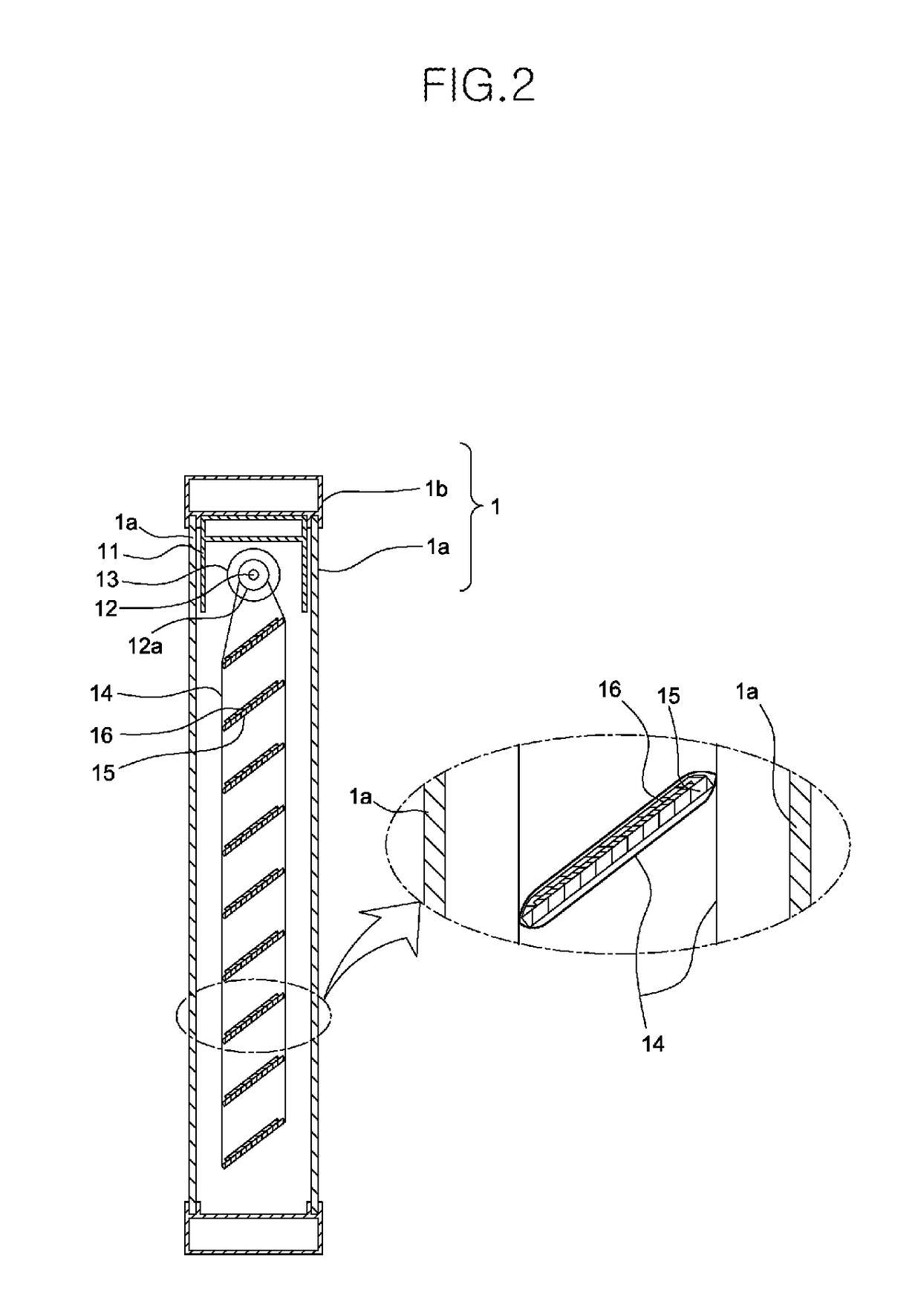
[0026]FIGS. 1 and 2 show a photovoltaic soundproof wall according to one preferred embodiment of the present invention, which is configured to have a plurality of soundproof members 1 each formed by surrounding the edge portions of two transparent sheets 1a with a main frame 1b and a plurality of posts 2 installed on ground in such a manner as to be equally spaced apart from one another for mounting the plurality of soundproof members 1 therebetween.

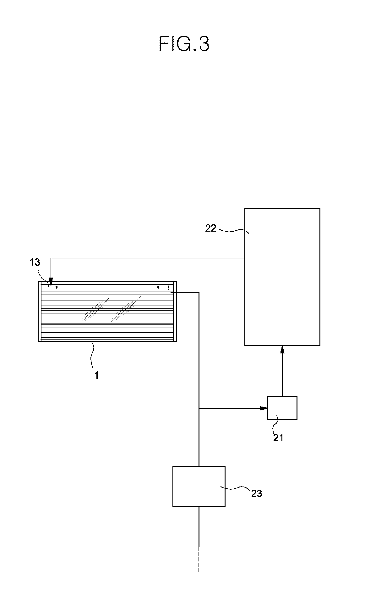
[0027]According to the present invention, the photovoltaic soundproof wall further includes a device for generating solar energy, and thus, a subframe 11 is mounted at the inside upper portion of the main frame 1b. A motor 13 is mounted at the inside of the subframe 11 for rotating a drive shaft 12, and as the motor 13 and the drive shaft 12 are activated, two slat drive co...


PUM


Abstract

The present invention relates to a photovoltaic soundproof wall having a plurality of soundproof members each formed by surrounding the edge portions of two transparent sheets with a main frame and a plurality of posts adapted to mount the plurality of soundproof members therebetween, the photovoltaic soundproof wall including: a subframe disposed inside the main frame; a motor disposed inside the subframe for rotating a drive shaft rotatably mounted inside the subframe; a power transmission unit adapted to transmit the rotary force of the motor; a plurality of slats spaced apart from each other vertically between the two transparent sheets in such a manner as to be moved collectively by the power transmitted from the power transmission unit; and a plurality of solar cells attached to the top surface of each of the plurality of slats.

Description

BACKGROUND OF THE INVENTION[0001]1. Field of the Invention[0002]The present invention relates to soundproof walls installed to provide the reduction of road traffic noises to the outside environments, and more particularly, to a photovoltaic soundproof wall that has functions of reducing road traffic noises and easily producing electricity therefrom.[0003]2. Background of the Related Art[0004]Generally, traffic noises on roads are high, and so as to reduce the road traffic noises, thus, soundproof walls are installed along both sides of the road, thereby preventing the road traffic noises from being transferred to the outside.[0005]Conventional soundproof walls, for example, are formed of relatively thick panels capable of efficiently reducing road traffic noises therefrom, but the formation of the relatively thick panels fails to allow the outside appearance of the road to be seen by the occupants of the vehicle.[0006]According to another example of the conventional soundproof wall...

Claims


Application Information

Patent Timeline
Patent Type & Authority Patents(United States)
IPC IPC(8): B64F1/26F24J2/38F24J2/40F01N5/00H01L31/00H01L31/042F24S50/20
CPCE01F8/0023H02S20/21F24J2/541F24S30/425Y02E10/50E01F8/00F21S9/03H02S20/32H01L31/043
Inventor PARK, JAE SUNG
Owner PARK JAE SUNG
Why Eureka
Try Eureka