
Friction welding apparatus, system and method

a welding apparatus and friction welding technology, applied in the field of metal fusion, can solve the problems of reducing so as to reduce the amount of circumferential friction stir welding used, increase the efficiency of welding, and reduce the effect of manpower

Active Publication Date: 2012-02-28
UNITED LAUNCH ALLIANCE
View PDF124 Cites 20 Cited by
  • Summary
  • Abstract
  • Description
  • Claims
  • Application Information

AI Technical Summary

Benefits of technology

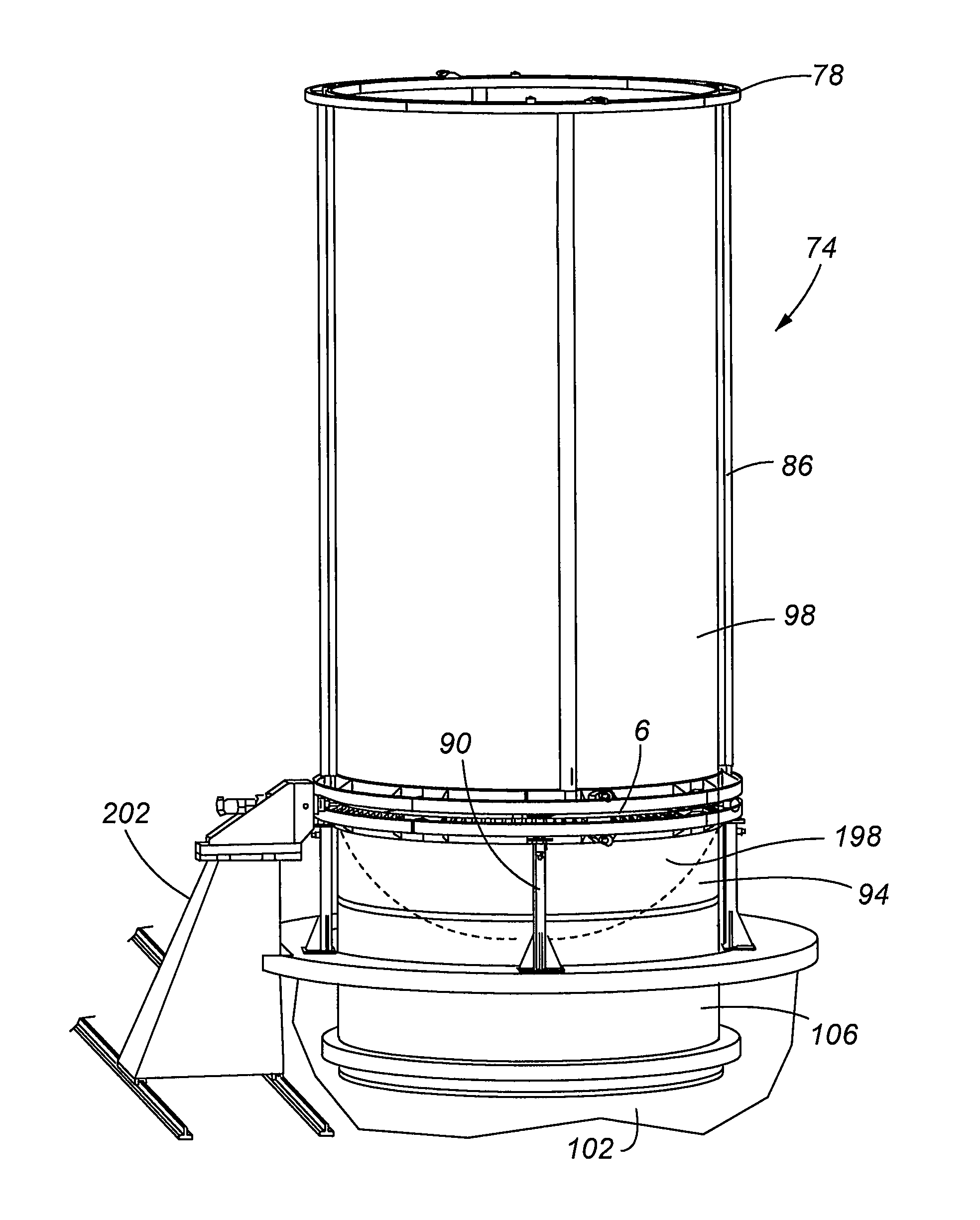
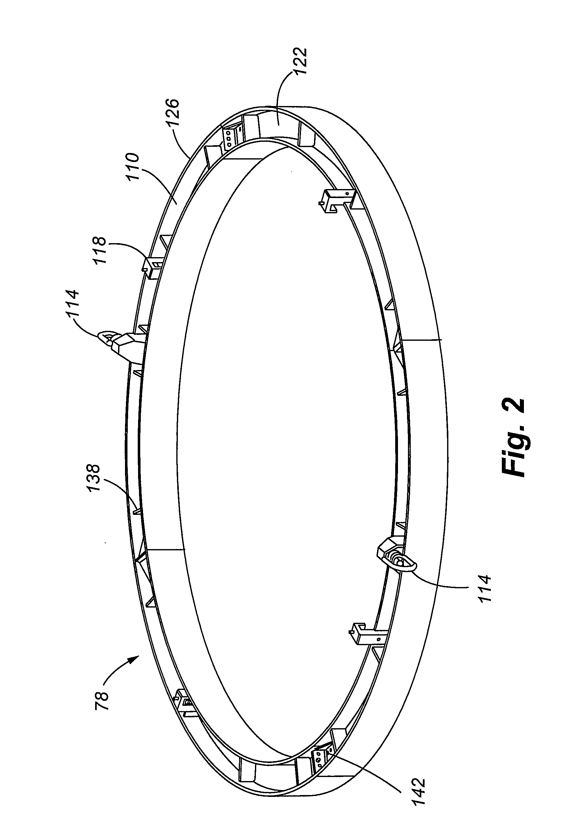
The present invention provides an apparatus, system, and method for welding two cylindrical members without using an internal mandrel. The apparatus includes a rotating tool that is moved relative to the joint between the two members. The tool generates friction heat that melts the material and causes the work pieces to fuse together. The system includes externally-situated rings that stiffen the exterior of the cylinders with the tool in between. The rings help counteract loads generated by the tool and also secure the work pieces relative to each other. The method eliminates the need for an internal mandrel or other internal support for the hardware, reducing costs and safety risks. The method also reduces weld cracking and allows for welds that span the entire thickness of the work pieces.

Problems solved by technology

Further, this technique also provides welds with extremely low dimensional distortion.
Friction between the rotating pin and work pieces causes localized heating and plasticizing of the material adjacent to the pin.
One drawback with friction stir welding is associated with the considerable force that must be exerted by the stir welding tool on the work piece.
Without the use of a counteracting backing member, tank distortions and inadequate weld penetration can result.
Another disadvantage with friction stir welding is that the end weld is incomplete because a hole associated with the pin remains when the friction stir welding tool is removed from the joint.
It is a related disadvantage of friction stir welding that the backing member must be removed after welding is completed.
After welding of a closed vessel such as a tank, access to the interior of the welded tank is often limited.
In some instances, access doors or hatches are provided that give access into the welded tank, but often these penetrations are typically small to facilitate proper closing of the tank.
Accordingly, heavy duty backing mandrels must often be removed from very small openings in the tank, an operation that is very difficult and time consuming.
Further, any contact between the backing tools and the tank may cause damage requiring expensive retesting and requalification of the propellant tank.
These measures obviously increase the cost of performing the weld operation.

Method used


Image

  • Friction welding apparatus, system and method
  • Friction welding apparatus, system and method
  • Friction welding apparatus, system and method

Examples


Embodiment Construction

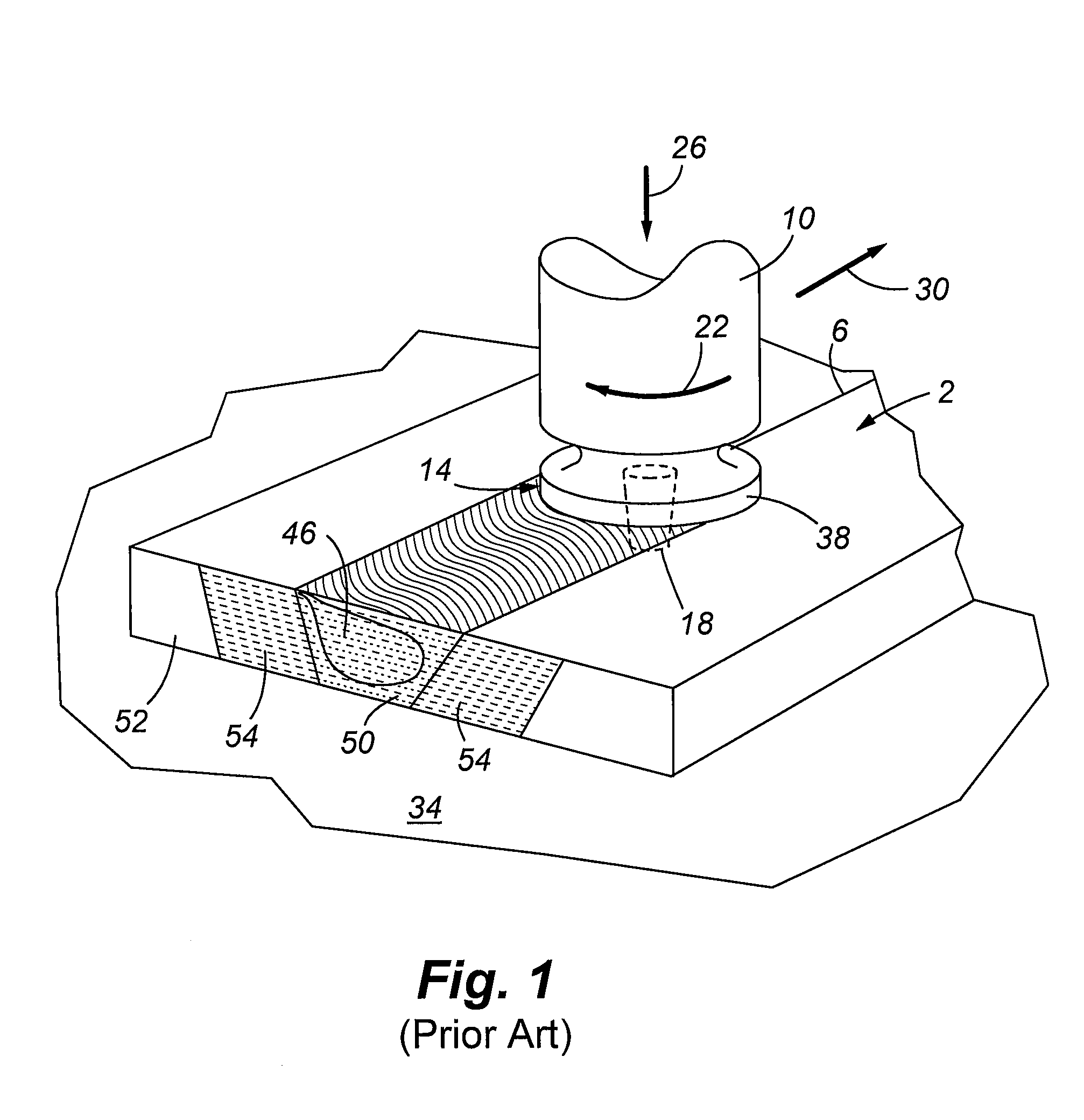
[0059]Referring now to FIG. 1, a prior art friction stir weld technique is illustrated wherein work pieces 2 are abutted to form a joint 6 therebetween. A friction stir welding tool includes a head 10 with associated shoulder 14 and pin 18. In practice, the shoulder 14 is placed on the work pieces 2 and the pin 18 is placed within the joint 6 after sufficient heat is generated by the spinning tool to allow penetration thereof. The head 10 is then forced downwardly onto the work pieces 2 as indicated by arrow 26 and is transitioned relative thereto 30. One skilled in the art will appreciate that the work pieces 2 may also move relative to the rotating head 10. The force 26 generated by the head 10 is reacted by a backing bar 34. As the head 10 is rotated and moved forward in the direction 30, friction is generated by the shoulder 14 and the pin 18 which keeps the metal of a portion of both work pieces 2 such that metal adjacent to a leading edge 38 of the shoulder 14 is moved / displac...


PUM

PropertyMeasurementUnit
thickaaaaaaaaaa
distanceaaaaaaaaaa
distanceaaaaaaaaaa

Abstract

A friction stir welding apparatus is provided herein. More specifically, traditional friction stir welding requires a rotatable head that is forced against a plurality of work pieces to bond the same. The rotational and normal forces generated by the friction stir welding tool are generally reacted by a backing plate, anvil, mandrel or other mechanisms, such hardware are subject to the applied forces and are often supported with additional internal supports. Conversely, an apparatus for performing a friction stir weld is described that omits the need for such a backing member and internal supports as it is performed using a self reacting pin tool.

Description

CROSS REFERENCE TO RELATED APPLICATIONS[0001]This application is a continuation of U.S. patent application Ser. No. 12 / 755,176 which was filed on Apr. 6, 2010, now abandoned and is hereby incorporated in its entirety by reference.FIELD OF THE INVENTION[0002]Embodiments of the present invention are related generally to metal fusion using a dynamic weld head to bond arcuate work pieces. More specifically, a weld fixture with external support rings holds the work pieces and a self-reacting friction stir welding tool bonds cylindrical shaped work pieces wherein a backing member is not required to counteract forces generated by the weld tool.BACKGROUND OF THE INVENTION[0003]Friction stir welding is a beneficial metal bonding technique wherein materials such as aluminum 7075, various alloys of aluminum / lithium and other similar materials previously considered to be unweldable, can be bonded. Friction stir welding also forms joints that possess material properties similar to those of the p...

Claims


Application Information

Patent Timeline
Patent Type & Authority Patents(United States)
IPC IPC(8): B23K20/12B23K37/04
CPCB23K37/0533
Inventor POTTER, DAVID M.HANSEN, RICHARD K.
Owner UNITED LAUNCH ALLIANCE
Learn More