Aircraft configuration for micro and mini UAV

a micro- and mini-uav technology, applied in the field of tandem aircraft arrangement, can solve the problems of low flight speed, research and design effort, and inability to achieve the aerodynamic design of such small vehicles by well-developed methods applied to conventional aircra

Active Publication Date: 2012-02-28
ISRAEL AEROSPACE IND
View PDF35 Cites 46 Cited by
  • Summary
  • Abstract
  • Description
  • Claims
  • Application Information

AI Technical Summary

Problems solved by technology

The aerodynamic design of such small vehicles is not tractable by well-developed methods applied to conventional aircraft, mainly due to the low Reynolds number of their flight (2*104-3*105), and the requirement of low flight speed, which is comparable with moderate wind speeds, such as 10-20 m / s.
Very intensive research and design effort takes place in the Micro-UAV (MAV) applications.
There is a clear conflict between constrains imposed on dimensions of Micro and Mini UAV and requirements to fly at reduced airspeeds with acceptable flying qualities and maneuver capabilities.
Typical configurations that try to achieve maximum exploitation of the allowable area (rectangular, delta, ogive wings, etc.), suffer from poor aerodynamic efficiency, low values of maximum lift and problematic stability and control characteristics.
The flight of these types of configurations relies massively on sophisticated flight control, while their performance is penalized by excessive weight of the battery (electric propulsion case) that should be carried for overcoming its poor aerodynamic efficiency.
Typical configurations of MUAV use overpowered engines for overcoming its poor aerodynamics efficiency and suffer from excessive weights of batteries, engine plant and airframe.
In flight, this results in increased air speed, which harms loitering performance, take off / landing characteristics and quality of video display.

Method used


Image

  • Aircraft configuration for micro and mini UAV
  • Aircraft configuration for micro and mini UAV
  • Aircraft configuration for micro and mini UAV

Examples


Embodiment Construction

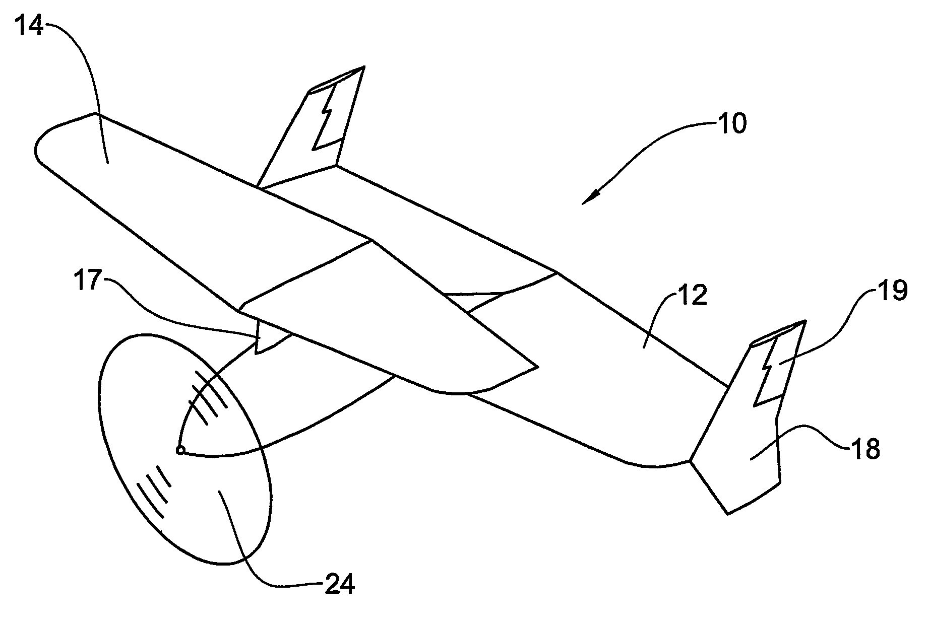
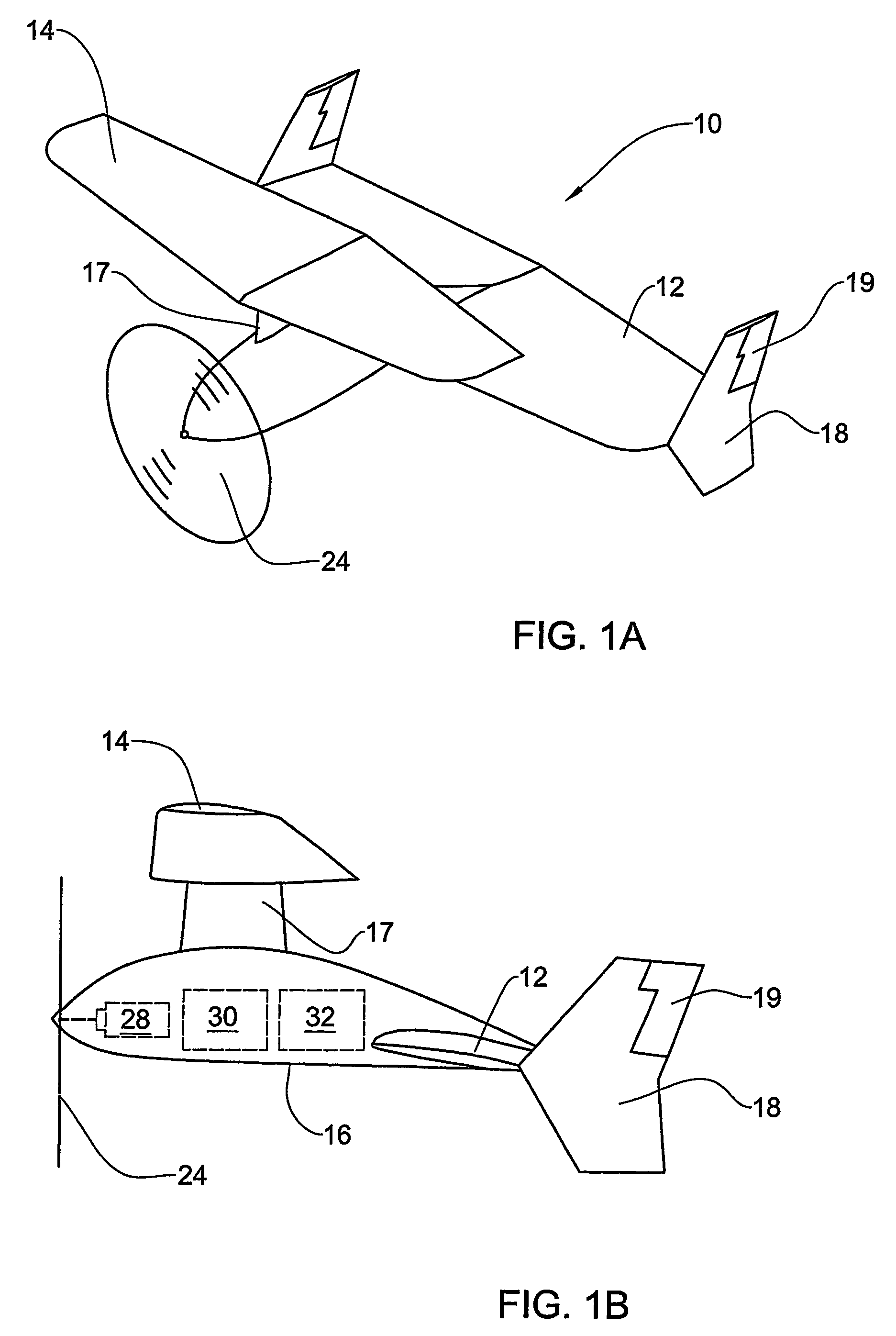
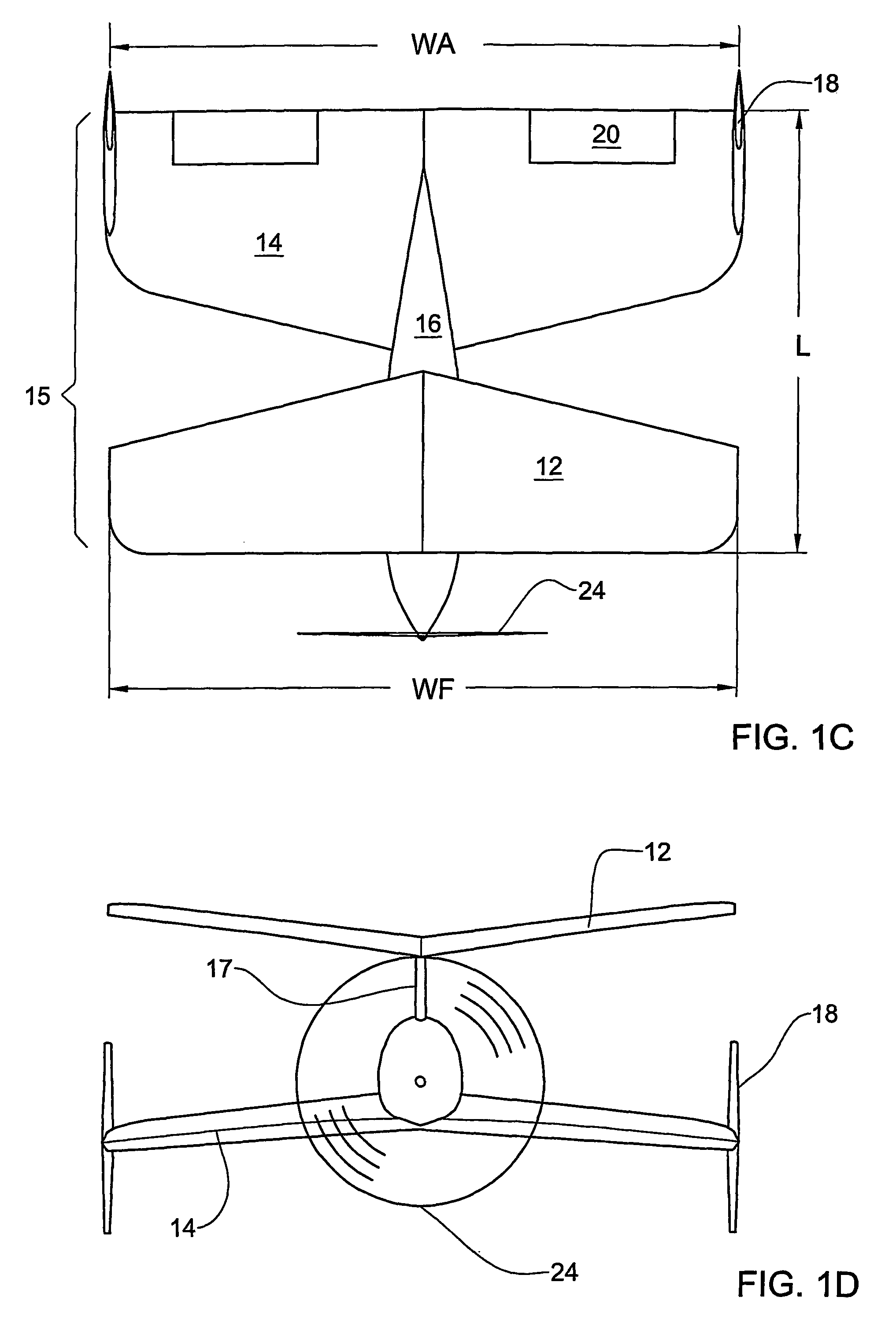
[0075]With reference to FIGS. 1A, 1B, 1C and 1D, there is shown an aircraft arrangement “X-plane” of a self-propelled Mini- or Micro-UAV 10 comprising a fore wing 12 and an aft wing 14 in tandem arrangement 15, mounted on a fuselage 16.

[0076]The aft wing 14 is mounted on the fuselage 16 as lower wing and the forewing 12 is mounted on a pylon 17 to the fuselage 16 as upper wing.

[0077]The aft wing 14 has swept-tapered planform with negative (downward) dihedral angle, with control surfaces (elevons) 20. The aft wing also has side panels 18 with rudder controls 19. The forewing 12 has also tapered planform but with negative sweep, and dihedral with positive (upward) dihedral angle.

[0078]The X-plane 10 includes also a tractor propeller 24 with power plant 28, batteries 30, payload 32 and others components (not illustrated). The wings and the other elements of the UAV are disposed so as to provide longitudinal stability.

[0079]The two wings 12 and 14 of the X-plane have moderate aspect rat...


PUM


Abstract

An aircraft arrangement for Mini or Micro UAV comprising a fore wing (14) and an aft wing (12) in tandem closed-coupled arrangement. The aft wing (12) has side panels (18) and control surfaces (19), and tapered planform with positive sweep, while the fore wing (14) has non-positive trailing edge sweep. The fore wing (14) and the aft wing (12) are disposed at different height, and the aircraft arrangement has no other wings or tail arrangements.

Description

CROSS-REFERENCE[0001]This is a National Phase Application filed under 35 U.S.C. 371 of International Application No. PCT / IL2004 / 000668, filed Jul. 22, 2004, the entire content of which is hereby incorporated herein by reference in its entirety.FIELD OF THE INVENTION[0002]This invention relates to tandem aircraft arrangements, in particular for application in Micro and Mini UAV (Unmanned / Unihabited Aircraft Vehicles)BACKGROUND OF THE INVENTION[0003]The advance of technology in the end of 20th century, especially in micro-technologies, including micro-mechanical systems, communication and control devices, made it feasible to design and manufacture unmanned aircraft capable of performing various military and civilian missions. In 2001, about 50 US companies, academic institutions, and government organizations have been developing over 150 UAV designs. About 115 of these designs are flying, while some 26 models of UAV's are in exploitation or ready for production. Most of the UAV used t...

Claims


Application Information

Patent Timeline
Patent Type & Authority Patents(United States)
IPC IPC(8): B64C39/12B64C39/02B64D15/16
CPCB64C39/028B64D15/163B64C2201/028B64C2201/165B64C2201/104B64U10/25B64U30/10B64U50/13
Inventor SHEPSHELOVICH, MICHAELSLETEAN, MARIOSTEINBUCH, MOSHELEVY, DAVID ELI
Owner ISRAEL AEROSPACE IND
Why Eureka
Try Eureka