
Layer application device for an electrostatic layer application of a building material in powder form and device and method for manufacturing a three-dimensional object

a technology of building materials and application devices, which is applied in the direction of additive manufacturing processes, coatings, chemistry apparatuses and processes, etc., can solve the problems of cracking or deformation, disadvantageous effects on the aspect ratio and the dimensional accuracy of the object to be formed,

Active Publication Date: 2012-02-28
3D MICROPRINT +1
View PDF26 Cites 94 Cited by
  • Summary
  • Abstract
  • Description
  • Claims
  • Application Information

AI Technical Summary

Benefits of technology

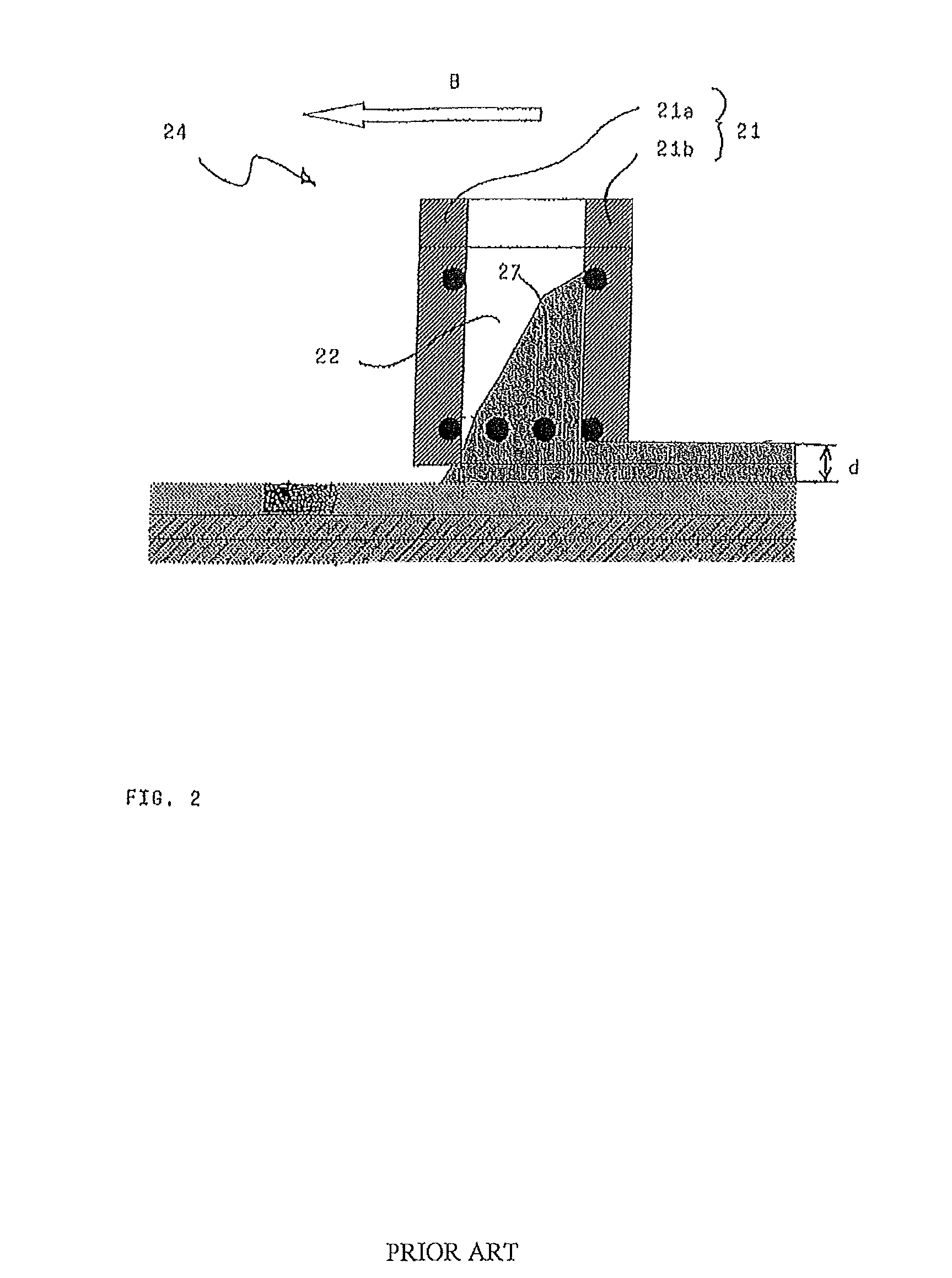
[0013]In all methods of the prior art a blade, a roller or a doctor is used for the layer application. However, the blade, the doctor or the roller in all cases applies mechanical force not only to the powder. When the powder layer has been applied onto a previously solidified layer of the part to be manufactured, then inevitably portions of the part that are already present are subjected to this force, which in general acts in a shearing way. From this a crack or a deformation may result, in particular in fragile structures or thin-wall structures. This has disadvantageous effects on the aspect ratio and the dimensional accuracy of the object to be formed.
[0014]The object of the invention is to provide a device for a contact-free layer application, in which the above described problems no longer occur. In particular, a thereby optimized device for a layer-wise manufacturing of parts by means of sintering as well as a respective method shall be provided.
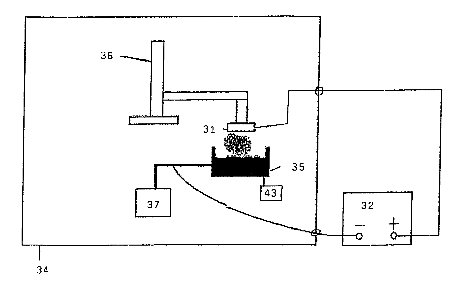
[0015]The object of the invention is achieved by a device for applying powder onto an application surface having a powder container (35) and a voltage source (32) for applying a voltage between the powder container (35) and the application surface, wherein the powder container (35) at least partially consists of a conductive material and the powder container (35) has an opening (35a) or is completely open at its side facing the application surface, when a voltage is applied.
[0016]The device of the present invention also can comprise one or more of the following features:
[0017]a) a positioning device (37) for adjusting the distance between the powder container (35) and the application surface such that for an applied voltage an electric field strength is high enough to transport the powder particles from the powder container to the application surface;
[0018]b) the adjustable field strength is higher than 1000 V / m;

Problems solved by technology

From this a crack or a deformation may result, in particular in fragile structures or thin-wall structures.
This has disadvantageous effects on the aspect ratio and the dimensional accuracy of the object to be formed.

Method used


Image

  • Layer application device for an electrostatic layer application of a building material in powder form and device and method for manufacturing a three-dimensional object
  • Layer application device for an electrostatic layer application of a building material in powder form and device and method for manufacturing a three-dimensional object
  • Layer application device for an electrostatic layer application of a building material in powder form and device and method for manufacturing a three-dimensional object

Examples


first embodiment

[0049]FIGS. 3 and 4 show a first embodiment of the invention. In FIGS. 3 and 4 a layer application device according to the invention is shown that is used in a laser sintering device. Here, FIG. 3 shows the laser sintering device during the layer application and FIG. 4 shows the same device during the layer solidification.

[0050]A building container 34, in which a three-dimensional object is manufactured layer-wise on a building platform 31 is shown in detail. The building platform 31 is mechanically connected to a lifting device 36, wherein the lifting device is able to move the building platform in a vertical direction up and down. In FIG. 3 below the building platform 31a powder container 35 with powder that shall serve as a building material for the building-up of the object, is arranged. By means of a high-voltage source 32a high-voltage is applied between the building platform 31 and the powder container 35, which high-voltage typically is in a range from 100 V to 40 kV, for ex...

second embodiment

[0059]In order to prevent the powder particles from coming off the building platform 1, which is facing downward according to embodiment 1, in the course of time, it is advantageous to have the building platform 1 facing downwards only during the powder application. According to a second embodiment, which is shown in FIG. 5, the building platform 31 therefore is no longer rigidly connected to the lifting device 36, but can be rotated around a horizontal axis 42 by means of a rotating device 41. Thereby it is possible to turn the building platform up via a rotation around the axis of rotation 42 after the completion of the application procedure, so that the applied layer faces the beam entrance window. Here, the building platform 31 is spatially separated from the mounting at the lifting device 36 by means of an insulator 33, which at the same time electrically decouples the building platform from the lifting device. With regard to the illustration of FIG. 5 it has to be noted that t...

third embodiment

[0062]FIG. 6 shows a view of a device according to a third embodiment of the invention as seen from a position on the axis of rotation 42.

[0063]Building platforms 31a, 31b, 31c, 31d that are arranged around the axis of rotation 42 having an angle of 90° to one another can be seen. Except this plurality of building platforms together with their respective mountings the device according to the third embodiment is identical to the one of the second embodiment.

[0064]According to the third embodiment it is for example possible that during the powder application onto the building platform 31a simultaneously the powder layer that has been previously applied onto the building platform 31c is exposed from above. This leads to a reduction of the building time. Though in FIG. 6 four building platforms are shown as an example, it is as well possible to use a different number of building platforms, in particular two building platforms opposite to one another. Moreover, in the third embodiment th...


PUM

PropertyMeasurementUnit
angleaaaaaaaaaa
voltageaaaaaaaaaa
grain sizeaaaaaaaaaa

Abstract

A device and a method for applying powder onto an application surface has a powder container (35) and a voltage source (32) for applying a voltage between the powder container and the application surface, wherein the powder container (35) at least partially consists of a conductive material and the powder container (35) has an opening (35a) or is completely open at its side facing the application surface when the voltage is applied.

Description

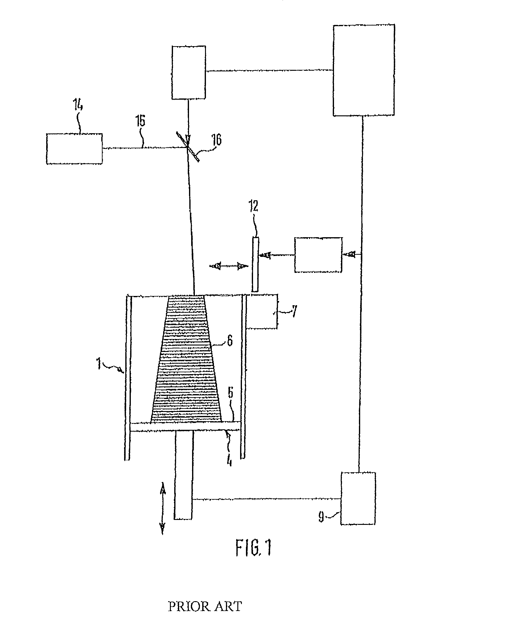
CROSS-REFERENCE TO RELATED APPLICATIONS[0001]Not ApplicableSTATEMENT REGARDING FEDERALLY SPONSORED RESEARCH OR DEVELOPMENT[0002]Not ApplicableREFERENCE TO A SEQUENCE LISTING[0003]Not ApplicableBACKGROUND OF THE INVENTION[0004](1) Field of the Invention[0005]The invention is related to a layer application device for an electrostatic layer application of a building material in powder form and in particular to a device and a method for a layer-wise manufacturing of a three-dimensional object, which device and method apply the layer application device.[0006](2) Description of Related Art[0007]A device and a method for the manufacturing of a three-dimensional object by selective laser sintering are for example known from U.S. Pat. No. 5,908,569. A respective device is shown in FIG. 1 and will be briefly described in the following.[0008]The laser sintering device shown in FIG. 1 has a container 1 that is open to the top, in which a support 4 for supporting the object 6 to be formed is pro...

Claims


Application Information

Patent Timeline
Patent Type & Authority Patents(United States)
IPC IPC(8): B05D1/30B29C67/00
CPCB22F3/003B22F3/1055B29C67/0077B22F2999/00B22F2202/06B22F2003/1056B29C64/153B33Y40/00B33Y10/00B33Y30/00Y02P10/25B22F10/28B22F12/30B22F12/50B22F12/37
Inventor PAASCHE, NORMANBRABANT, THOMASSTREIT, STEFAN
Owner 3D MICROPRINT
Learn More