Methods and systems for altering fluorescent intensities of a plurality of particles

a technology of fluorescent intensities and systems, applied in the field of methods and systems for altering fluorescent intensities of a plurality of particles, can solve the problems of increasing the cost and/or difficulty of producing the platform, adding complexity to the system, and difficult to produce particles exhibiting fluorescent intensities, so as to reduce fluorescent emissions

Active Publication Date: 2012-02-28
LUMINEX
View PDF23 Cites 4 Cited by
  • Summary
  • Abstract
  • Description
  • Claims
  • Application Information

AI Technical Summary

Benefits of technology

[0011]An embodiment of an apparatus for altering fluorescent emissions of particles includes a vessel configured to contain a plurality of particles and a means for setting particles contained within the vessel in motion. The apparatus further includes a subsystem with a light source system and an optical system collectively configured to direct light toward the vessel and at a spectral window (i.e., wavelength or band of wavelengths) which is configured to isotropically and substantially simultaneously lessen the fluorescent emissions of each of the particles contained within the vessel.

Problems solved by technology

The inclusion of additional dyes and / or dye intensities, however, adds complexity to the system, which can greatly contribute to increasing the expense and / or difficulty of producing the platform.
In some cases, however, it may be difficult to produce particles exhibiting fluorescent intensities which fall into predetermined detection windows.
As such, it may theoretically possible to produce hundreds of particle categories, but in practice such a number of categories is difficult to achieve.
Furthermore, dyed particles may not exhibit expected fluorescence emissions for a number of other reasons including varying characteristics (e.g., size and / or composition) of the particles prior to being dyed.
In any case, particles that exhibit fluorescence emissions that do not fit within a selected detection window are typically scrapped or discarded, increasing the time and expense of producing a population of particles for a multiplexing scheme.

Method used


Image

  • Methods and systems for altering fluorescent intensities of a plurality of particles
  • Methods and systems for altering fluorescent intensities of a plurality of particles
  • Methods and systems for altering fluorescent intensities of a plurality of particles

Examples


example 1

Alteration of Fluorescence Emissions of a Plurality of Particles

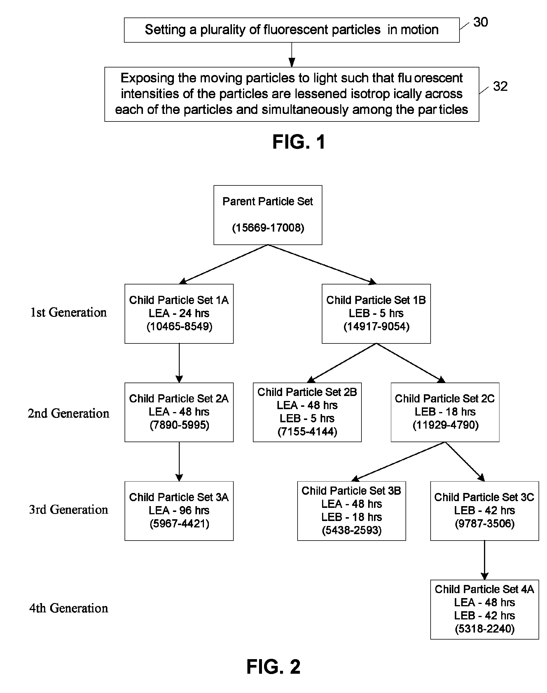
[0046]Particles were each dyed with both Dye A and Dye B to form a parent particle set. In this example, 2,4-bis[2,4-dimethylpyrrole]cyclobutenediylium-1,3-dioxolate served as “Dye A” and 2,4-bis[1,1-dimethyl-2-(1-H-benz[e]indolinylidenemethyl)]cyclobutenediylium-1,3-dioxolate served as “Dye B”. Other dyes, however, may be used with the photo-bleaching process described herein. The fluorescent emissions of the particles were measured using a Luminex 100 instrument available from Luminex Corporation of Austin, Tex. The fluorescent intensities for each dye are given in units of MFI with the intensity of Dye A reported by the A channel and the intensity of dye B reported by the B channel. The parent particle set was exposed to various light conditions in order to generate different regions by selective photo-bleaching. One subset of the parent particle set was diluted to 500,000 microspheres / mL and photo-bleached using a r...

example 2

Correction of Fluorescence Emissions of a Plurality of Particles

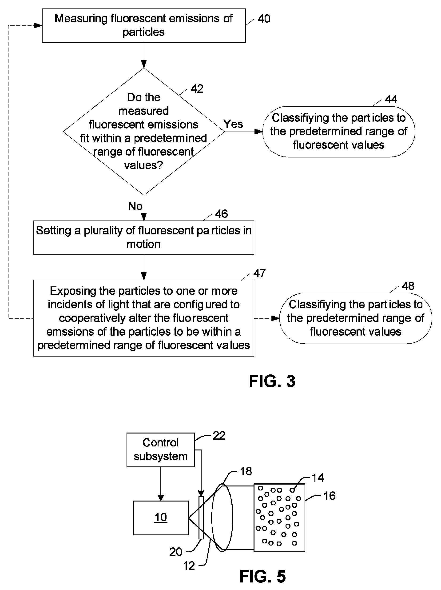
[0051]After encoding a subset of the encoded particles, they are tested against the predefined fluorescent targets. If a set of encoded particles does not fit any of the predefined targets, the set cannot be used in combination with other sets that are targeted correctly. However, using small exposures of light, the population of particles may have their fluorescent emissions altered to be within one of the predefined spaces. In an exemplary embodiment referencing the scatter plots of FIGS. 4A-4F, exposure to a red LED moves the improperly encoded particle population down the channel B axis while exposure to a green LED moves the population diagonally down both the channel A and channel B axes. The following sequence of light exposures was used in such an example to move the particle population within a predefined space. It is noted that such a sequence of exposures is exemplary and, therefore, the methods described her...


PUM

PropertyMeasurementUnit
sizesaaaaaaaaaa
sizesaaaaaaaaaa
fluorescent emissionsaaaaaaaaaa

Abstract

A method for altering fluorescent emissions of particles includes setting the particles in motion and exposing the moving particles to light such that fluorescent intensities of the particles are lessened isotropically and substantially simultaneously. Another method includes measuring fluorescent emissions of particles, determining the measured fluorescent emissions do not collectively fit within a first predetermined range of fluorescent values, and exposing the particles to one or more incidents of light that are configured to cooperatively alter the fluorescent emissions of the particles to be within a second predetermined range of fluorescent values. An embodiment of an apparatus includes a vessel configured to contain a plurality of particles and a means for setting the particles in motion. The apparatus further includes an illumination subsystem configured to direct light toward the vessel and at a spectral window (i.e., wavelength or band of wavelengths) which is configured to isotropically and substantially simultaneously lessen the fluorescent emissions of each of the particles.

Description

BACKGROUND OF THE INVENTION[0001]1. Field of the Invention[0002]This invention generally relates to methods and apparatuses for encoding particles and, more specifically, to methods and systems for altering fluorescent intensities of a plurality of particles.[0003]2. Description of the Related Art[0004]The following descriptions and examples are not admitted to be prior art by virtue of their inclusion within this section.[0005]Spectroscopic techniques are widely employed in the analysis of chemical and biological systems. Most often, these techniques involve measuring the absorption or emission of electromagnetic radiation by the material of interest. One application is in the field of microarrays, which is a technology exploited by a large number of disciplines including the combinatorial chemistry and biological assay industries. Luminex Corporation of Austin, Tex. has developed systems in which biological assays, for example, are performed on the surface of variously colored flu...

Claims


Application Information

Patent Timeline
Patent Type & Authority Patents(United States)
IPC IPC(8): G01J1/58G01N15/02G01N21/64G01N21/00
CPCG01N15/1456G01N2021/6439
Inventor LUGADE, ANANDA G.BERNARD, BRUCE J. C.HOFFACKER, KURT D.
Owner LUMINEX
Why Eureka
Try Eureka