Driver assistance system and method for checking the plausibility of objects

a technology of driver assistance and object, applied in the field of object plausibility check, can solve the problems of only accurate data, high accuracy and reliability requirements, and large source of risk, and achieve the effect of reliable plausibility check

Active Publication Date: 2012-02-28
ROBERT BOSCH GMBH
View PDF27 Cites 19 Cited by
  • Summary
  • Abstract
  • Description
  • Claims
  • Application Information

AI Technical Summary

Benefits of technology

[0015]Example embodiments of the present invention provide a method for checking the plausibility of an object that will allow a more reliable plausibility check of the objects located by the two position-finding systems.
[0018]The method according to example embodiments of the present invention in this manner avoids the uncertainties resulting from the difficulty of correctly assigning the position data obtained for various objects from the two position-finding systems.
[0019]For the comparison of the position data of the two position-finding systems, it is thus not necessary to have complex plausibility check algorithms but instead the plausibility check involves simply comparing two numerical values. The plausibility check may therefore be performed with a high reliability and nevertheless in an extremely short period of time, so that valuable time is saved with PSS systems in particular.
[0020]Example embodiments of the present invention are advantageous in particular when one of the two object position-finding systems is an FMCW radar (frequency-modulated continuous wave), which is already in use today as a radar object position-finding system in many driver assistance systems. With an FMCW radar, an intermediate frequency signal which indicates the frequency difference between the signal sent and the signal received is generated by mixing the signal reflected by such an object and received again by the sensor with the signal sent by this sensor at the reception time. The time to collision may be determined from this intermediate frequency signal. In this way, one of the two measured variables needed for the consistency check is obtained by a very rapid method, which has a low susceptibility to error.
[0026]With the method according to example embodiments of the present invention, the time to collision, which is obtained independently with the help of the second position-finding system, may now be utilized as an additional criterion for differentiating real objects from spurious objects. The time to collision represents a certain relationship between distance and relative speed for each object, and only in the case of real objects is this relationship consistent with the relationships obtained from the intermediate frequency signals on two frequency ramps. In this manner, example embodiments of the present invention make it possible to differentiate reliably between real objects and spurious objects.

Problems solved by technology

However, such systems make very high demands on the accuracy and reliability of the position-finding system because otherwise there may often be faulty deployment, which could in turn constitute a considerable source of risk.
One example of a system optimized for the longitudinal value is a radar system, which supplies relatively accurate measured values for the distance and relative speed of an object, but supplies only inaccurate data for the azimuth angle and thus the lateral position of the object even when the radar sensor has a certain angular resolution.
Such a system is capable of supplying relatively accurate data about the azimuth angle and the lateral extent of an object, but it allows only an inaccurate determination or estimate of the object distance, in particular with monocular systems, and the relative speed may be determined only indirectly by derivation of the inaccurate distance data over time.
A binocular video system allows a distance determination by triangulation, but it also yields only relatively inaccurate values, in particular at greater distances.
However, there remains a bit of uncertainty with regard to the question of whether or not the position data supplied by the two independent systems actually describe the same real object.
By using three or more different frequency ramps, the incidence of such spurious objects may be reduced but cannot always be suppressed completely.

Method used


Image

  • Driver assistance system and method for checking the plausibility of objects
  • Driver assistance system and method for checking the plausibility of objects
  • Driver assistance system and method for checking the plausibility of objects

Examples


Embodiment Construction

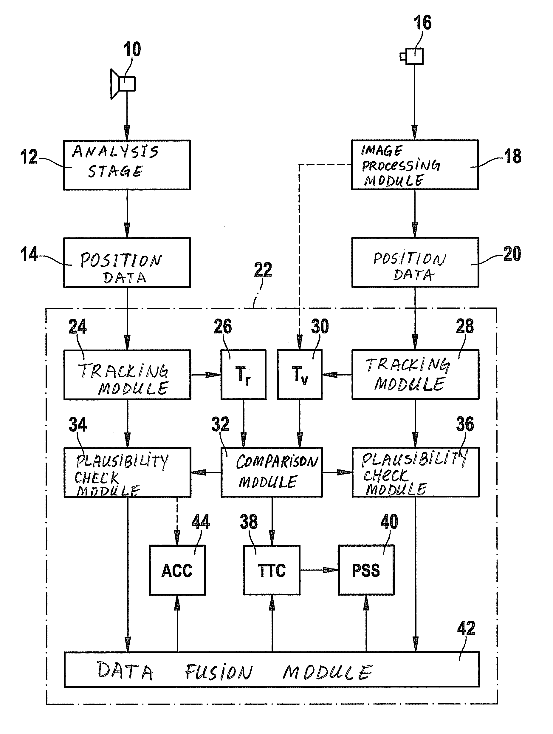
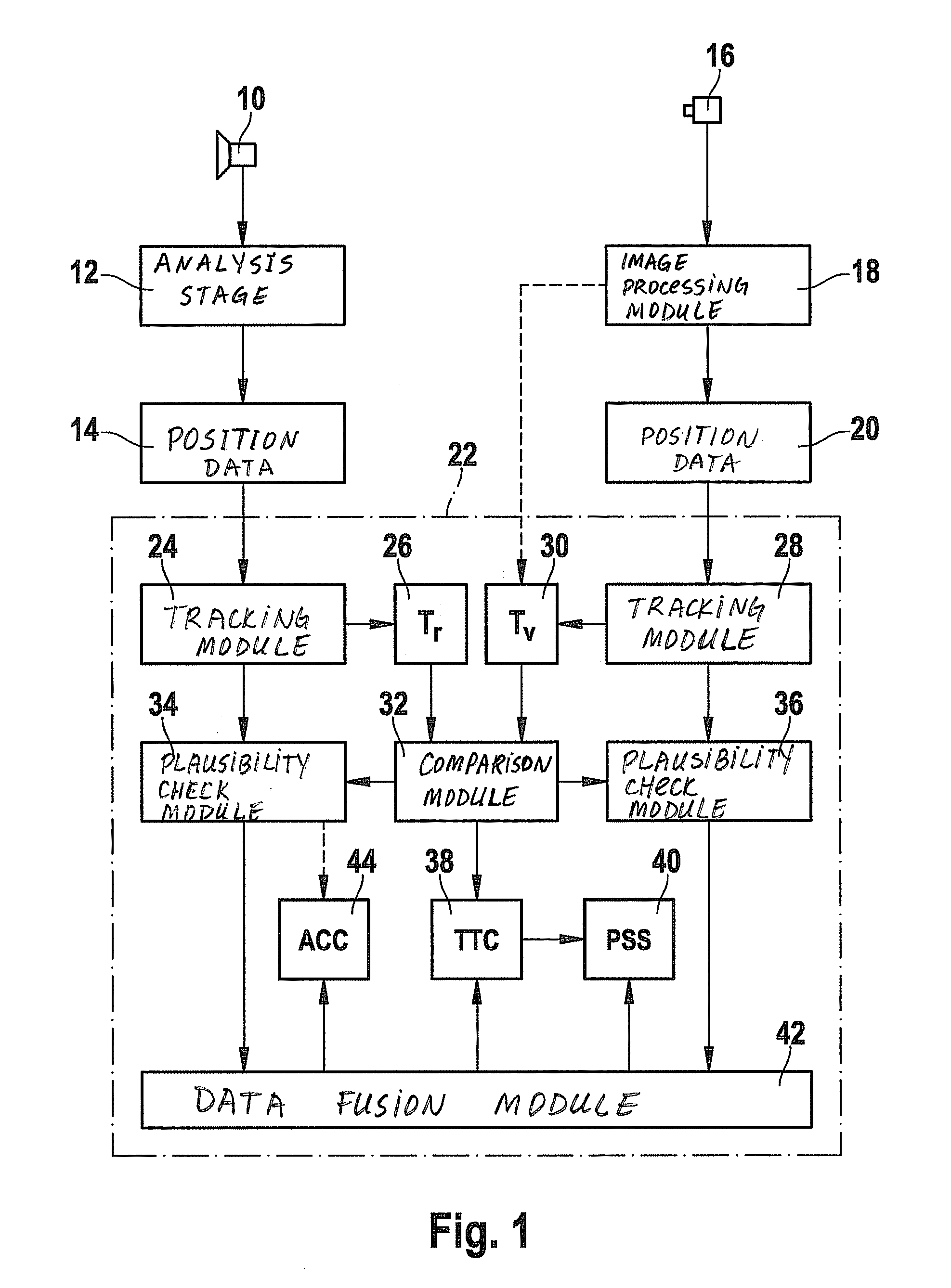
[0034]FIG. 1 shows a driver assistance system for a motor vehicle, namely in this example a combination of an adaptive cruise control (ACC) system and a predictive safety system (PSS), shown as a block diagram. This system includes two object position-finding systems that operate independently of one another for detection of the field in front of the vehicle equipped with the driver assistance system.

[0035]A first object position-finding system is formed by a radar sensor 10, an FMCW radar in the example shown here. Received radar signals are preprocessed in an analysis stage 12, thus yielding position data 14 for one or more located objects. Each object is described by a set of position data, including the distance, the relative speed and the azimuth angle of the object. The radar measurements are performed cyclically during a period on the order of 100 ms, so that position data 14 are updated in short intervals.

[0036]A monocular video system having a video camera 16, installed in ...


PUM


Abstract

In a method for checking the plausibility of objects in driver assistance systems for motor vehicles is described, two measured variables are derived from position data from two object position-finding systems of the vehicle that operate independently of one another, for an object located by the two position-finding systems, one variable for each position-finding system, these variables representing one and the same physical parameter, and the two measured variables are then checked for consistency, which is characterized by the fact that the parameter is the time to collision of the vehicle with the object, which is calculated in advance.

Description

CROSS REFERENCE TO RELATED APPLICATION[0001]This application was filed as International Patent Application No. PCT / EP2008 / 52562 on Mar. 3, 2008 and claims foreign priority benefits of German Patent Application No. 10 2007 018 470.2, filed Apr. 19, 2007.FIELD OF THE INVENTION[0002]The present invention relates to a method for checking the plausibility of objects in driver assistance systems for motor vehicles, in which two measured variables are derived from position data from two object position-finding systems of the vehicle that operate independently of one another for an object located by the two position-finding systems, one variable for each position-finding system, these variables representing one and the same physical parameter; in this method, the two measured variables are then checked for consistency. The subject matter of the present invention is also a driver assistance system equipped for implementing this method.BACKGROUND INFORMATION[0003]Examples of driver assistance...

Claims


Application Information

Patent Timeline
Patent Type & Authority Patents(United States)
IPC IPC(8): G01S13/93G01S13/931
CPCG01S11/12G01S13/867G01S13/931B60W2420/52G01S2013/9375G01S2013/9325G01S2013/93271
Inventor FOCKE, THOMASBECKER, JAN-CARSTENHILSEBECHER, JOERGZENDER, ARNEMUELLER-FRAHM, MARIOSPARBERT, JANSSCHOEBERL, THOMASOECHSLE, FREDGRIMM, ANDREASSIMON, ANDREAS
Owner ROBERT BOSCH GMBH
Why Eureka
Try Eureka