Memory system and method using a memory device die stacked with a logic die using data encoding, and system using the memory system

a memory system and logic die technology, applied in the field of memory devices, can solve problems such as idle computer systems, slow computer system performance, and exacerbated problems

Active Publication Date: 2012-02-28
MICRON TECH INC
View PDF61 Cites 100 Cited by
  • Summary
  • Abstract
  • Description
  • Claims
  • Application Information

AI Technical Summary

Problems solved by technology

Yet conventional DRAM devices often do not have the bandwidth to read and write data at these higher speeds, thereby slowing the performance of conventional computer systems.
This problem is exacerbated by the trend toward multi-core processors and multiple processor computer systems.
It is currently estimated that computer systems operating as high-end servers are idle as many as 3 out of every 4 clock cycles because of the limited data bandwidth of system memory devices.
In fact, the limited bandwidth of DRAM devices operating as system memory can reduce the performance of computer systems to as low as 10% of the performance of which they would otherwise be capable.
However, doing so usually requires that write data be serialized and read data deserialized at the memory device interface.
Another approach has been to simply scale up the size of memory devices or conversely shrink their feature sizes, but, for a variety of reasons, scaling has been incapable of keeping up with the geometric increase in the demand for higher data bandwidths.
Several other issues often arise in the design and use of memory devices.
One of these issues is power consumption.
In some applications, such as in portable electronic devices, power consumption is very important because it can seriously reduce the operating time of battery powered devices such as laptop computers.
Another issue that often arises is the inadvertent loss of data stored in memory devices, such as dynamic random access memory (“DRAM”) devices.
If DRAM devices are not refreshed frequently enough, data retention errors can occur.
Unfortunately, refresh consumes a substantial amount of power, thus making it desirable to minimize the frequency of refreshes.
As a result of this trade-off between power consumption and minimizing data errors, DRAM devices are often refreshed near the rate at which data retention errors can occur.
Data retention errors can also occur in other types of memory devices, such as flash memory devices, for different reasons.
Still another issue that often arises in the design of memory devices is minimizing the signal connections to the die of the memory device.
The area used by bond wire consumes space on the die that could be used for fabricating transistors to increase the capacity of the memory device.
The same problem also exists for the area consumed on a memory device die by through silicon vias (“TSVs”) connected to stacked memory devices.
Although doing so does to some extent alleviate the problem of limited bandwidth, it can exacerbate the other problems discussed above, including power consumption and consuming excessive die area with TSVs, particularly if ECC techniques are to be used to correct data retention errors.

Method used


Image

  • Memory system and method using a memory device die stacked with a logic die using data encoding, and system using the memory system
  • Memory system and method using a memory device die stacked with a logic die using data encoding, and system using the memory system
  • Memory system and method using a memory device die stacked with a logic die using data encoding, and system using the memory system

Examples


Embodiment Construction

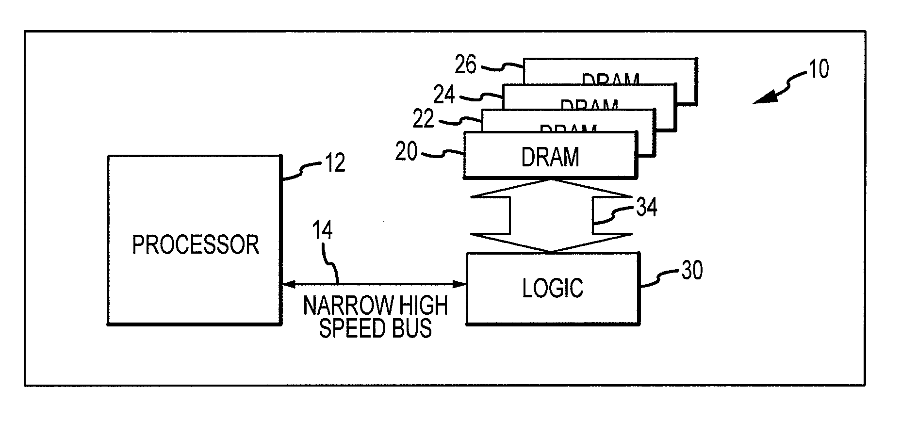
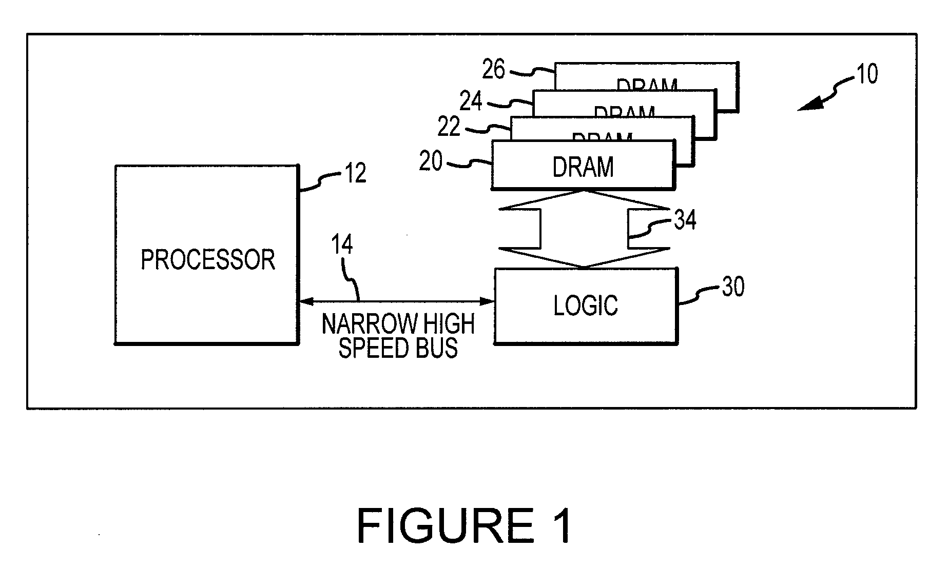
[0014]A computer system including a high-capacity, high bandwidth memory system 10 according to an embodiment of the invention is shown in FIG. 1. The memory system 10 is connected to a memory access device, such as a processor 12 through a relatively narrow high-speed bus 14 that is divided into downstream lanes and separate upstream lanes (not shown in FIG. 1). The memory system 10 includes 4 DRAM dice 20, 22, 24, 26, which may be identical to each other, stacked on top of each other. Although the memory system 10 includes 4 DRAM dice 20, 22, 24, 26, other embodiments of the memory device use a greater or lesser number of DRAM dice. The stacked DRAM dice 20, 22, 24, 26 are connected to a logic die 30, which serves as the interface with the processor 12. The logic die 30 can be physically positioned relative to DRAM dice 20, 22, 24, 26 in any order, such as by stacking the DRAM dice 20, 22, 24, 26 on top of the logic die 30. However, the logic die 30 could, for example, be position...


PUM


Abstract

A memory system and method using at least one memory device die stacked with and coupled to a logic die by interconnects, such as through silicon vias. One such logic die includes an ECC system generating error checking and correcting (“ECC) bits corresponding to write data. The write data are transmitted to the memory device dice in a packet containing a serial burst of a plurality of parallel data bits. The ECC bits are transmitted to the memory device dice using through silicon vias that are different from the vias through which data are coupled. Such a logic die could also include a data bus inversion (“DBI”) system encoding the write data using a DBI algorithm and transmitting to the memory device dice DBI bits indicating whether the write data have been inverted. The DBI bits are transmitted using through silicon vias that are shared with the ECC bits when they are unused for transferring the ECC bits.

Description

TECHNICAL FIELD[0001]This invention relates to memory devices, and, more particularly, in one or more embodiments to a memory system having a plurality of stacked memory device dice connected to a logic die in which data are coupled between the logic die and the memory device dice using data bus inversion.BACKGROUND OF THE INVENTION[0002]As memory devices of all types have evolved, continuous strides have been made in improving their performance in a variety of respects. For example, the storage capacity of memory devices has continued to increase at geometric proportions. This increased capacity, coupled with the geometrically higher operating speeds of electronic systems containing memory devices, has made high memory device bandwidth ever more critical. One application in which memory devices, such as dynamic random access memory (“DRAM”) devices, require a higher bandwidth is their use as system memory in computer systems. As the operating speed of processors has increased, proc...

Claims


Application Information

Patent Timeline
Patent Type & Authority Patents(United States)
IPC IPC(8): G06F11/00
CPCG06F11/1625G06F11/10
Inventor HARGAN, EBRAHIM
Owner MICRON TECH INC
Why Eureka
Try Eureka