Protective helmet having a microprocessor controlled response to impact

a protective helmet and microprocessor technology, applied in the field of protective helmets, can solve problems such as surface area change, and achieve the effect of preventing the brain from hitting the skull, softening or slowing such impa

Inactive Publication Date: 2012-03-06
FODEMSKI TROY ALLEN
View PDF11 Cites 64 Cited by
  • Summary
  • Abstract
  • Description
  • Claims
  • Application Information

AI Technical Summary

Benefits of technology

[0009]The present invention detects external impact to the helmet and then produces responsive forces to counter this external impact. The purpose of countering the external impact is to prevent the brain from hitting the skull, or at least soften or slow such impact because it is known that rapid movement of the brain against the skull causes concussive trauma to the brain.
[0010]A feature of this system is to produce forces responsive to impact in a rapid and effective manner, which re-direct the forces associated with impact. In particular, the present invention provides a way of localizing the forces associated with impact on the shell of a helmet, which is particularly configured to dampen the impact forces.
[0012]One method of the present invention reduces concussive effects to the brain produced by impact on an outside surface of a protective helmet. The method includes sensing the magnitude and location of the impact, transmitting a first signal to the location of the impact, and in response to the first signal, adjusting fluid pressure in at least one cell disposed between the outside surface of the protective helmet and the head of the helmet wearer. In one embodiment of the invention, each cell is capable of rapid inflation, which inhibits penetration of the impact force into the head of a user, and instead, redirects the impact forces in the helmet shell. The redirected forces are localized primarily on the helmet shell and move through the shell like waves in a pool of water. Some of the waves meet at a point distant from the impact location.
[0013]The method further includes sequentially transmitting a second signal to a location on the helmet distant to the location of the impact, and in response to the second signal, adjusting fluid pressure at least one cell disposed between the outside surface of the protective helmet and the head of the helmet wearer at the location distant to the impact. This second phase of fluid pressure adjustment redirects the waves to assure that there is a minimal penetration of force inside the helmet, and instead the forces are localized to the shell of the helmet. In addition to redirecting forces to cause localization of forces on the helmet shell, the cells rapidly deflate to absorb any impact forces directed into the helmet. Deflating the cells also increases the time of impact, thus reducing the energy of impact, which is the traditional function of padding. Vents on the helmet dampen impact forces.
[0015]A system of the present invention includes a helmet for reducing the concussive effects of impact. The helmet protects the head of a user by generating forces responsive to impact to optimize the protective capabilities of the helmet.
[0016]The helmet includes an array of strain gauges attached within the helmet for detecting a strain profile resulting from impact. The helmet also includes an array of inflatable cells attached within the helmet, where at least one of the cells is associated spatially with each strain gauge. The cells are selectively inflatable for absorbing and redistributing impact forces and for generating forces responsive to impact. The force responsive to impact may be generated by both instant pressurization of the cell and by expression of fluid from the cell during deflation of the cell. A fluid conduit and a valve are attached to each cell for regulating cell internal pressure. Cell inflation may be sequenced to optimal system performance.

Problems solved by technology

This change to the surface area is a direct result of an external blow to the user's helmet.

Method used


Image

  • Protective helmet having a microprocessor controlled response to impact
  • Protective helmet having a microprocessor controlled response to impact
  • Protective helmet having a microprocessor controlled response to impact

Examples


Embodiment Construction

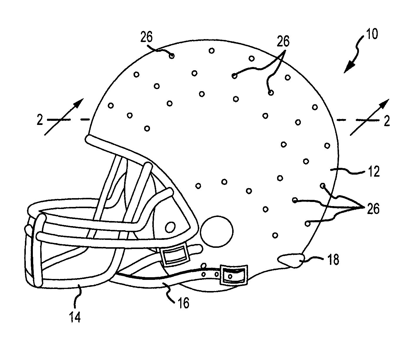
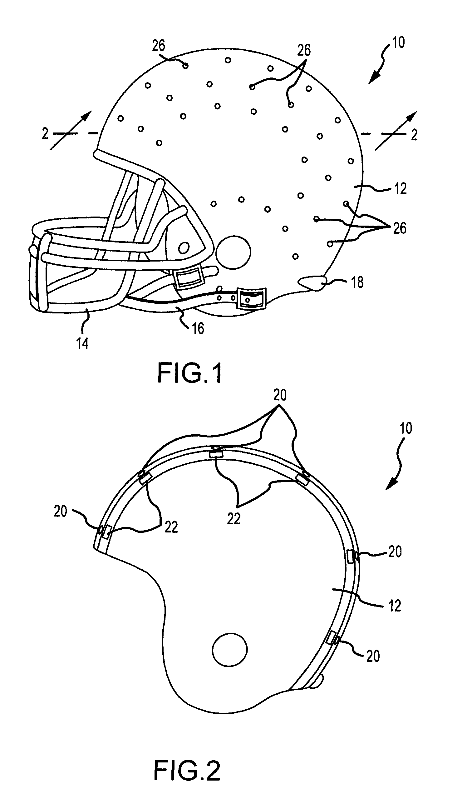
[0030]FIG. 1 shows a helmet 10. The helmet 10 is a gridiron football (football) helmet including a shell 12, a mask 14 mounted on the shell 12, and a chin strap 16 for holding the helmet 10 on the head of a user. The shell 12 includes a plurality of vents 26 to enable compressed fluid to be expressed through the shell 12.

[0031]The helmet 10 includes a fluid reservoir 18 mounted on a rear portion of the helmet 10 opposing the location of the mask 14. Positioning the fluid reservoir 18 in a position opposing the mask 14 reduces the likelihood of impact directly against the reservoir 18. The reservoir 18 is refillable.

[0032]FIG. 2 shows a cross-section of the helmet 10 as seen along the line 2-2 in FIG. 1 as seen in the direction of the arrows. The shell 12 includes an array of strain gauges 20 and an array of cells 22 mounted an inner surface of the shell 12. The array of strain gauges 20 and the array of cells 22 mount on the inner surface of the shell 12 to enable rapid replacement ...


PUM


Abstract

A method and system for reducing the concussive effects of impact. The system includes a helmet for protecting the head of a user. The helmet has a surface, an array of strain gauges attached on the surface for detecting an impact, an array of cells attached within the helmet and a fluid reservoir in fluid communication with the cells. Each cell is selectively inflatable to redirect impact forces to the shell of the helmet, and selectively deflatable to cushion a users head during impact. The process of inflation and deflation is enabled and optimized through the use of a microprocessor connected in operative communication with the array of strain gauges and with the valves. Accordingly, when the system detects impact, the microprocessor selectively signals at least some of the valves to rapidly change pressure in the cells near the impact.

Description

FIELD OF THE INVENTION[0001]This invention relates to helmets that protect users from impact, and particularly helmets that generate force responsive to impact to minimize adverse biomechanical and other effects of impact on the brain of a user.BACKGROUND OF THE INVENTION[0002]Concussive head trauma has been found to cause many degenerative brain diseases including chronic traumatic encephalopathy (CTE), a degenerative brain disease found in those who have a history of repetitive brain trauma, including concussions.[0003]Individuals with Chronic Traumatic Encephalopathy may show symptoms of dementia, which includes memory loss, aggression, confusion and depression. Such symptoms may appear within months of the trauma or many decades later. CTE has been commonly found in professional athletes participating in contact sports such as gridiron football, ice hockey and professional wrestling. CTE may also result from motor vehicle collisions and battlefield injuries. Most CTE patients ha...

Claims


Application Information

Patent Timeline
Patent Type & Authority Patents(United States)
IPC IPC(8): A42B3/00
CPCA42B3/046A42B3/121
Inventor FODEMSKI, TROY ALLEN
Owner FODEMSKI TROY ALLEN
Why Eureka
Try Eureka