
Method of reducing power consumption of a radio badge in a boundary detection localization system

a technology of localization system and radio badge, which is applied in the direction of burglar alarm mechanical actuation, electromagnetic radiation sensing, instruments, etc., can solve the problems of high sampling rate, unnecessary high power requirements, and direct proportional energy consumption of mobile units, and achieve the effect of reducing the power consumption of radio badges

Active Publication Date: 2012-03-06
NAT TAIWAN UNIV
View PDF2 Cites 9 Cited by
  • Summary
  • Abstract
  • Description
  • Claims
  • Application Information

AI Technical Summary

Benefits of technology

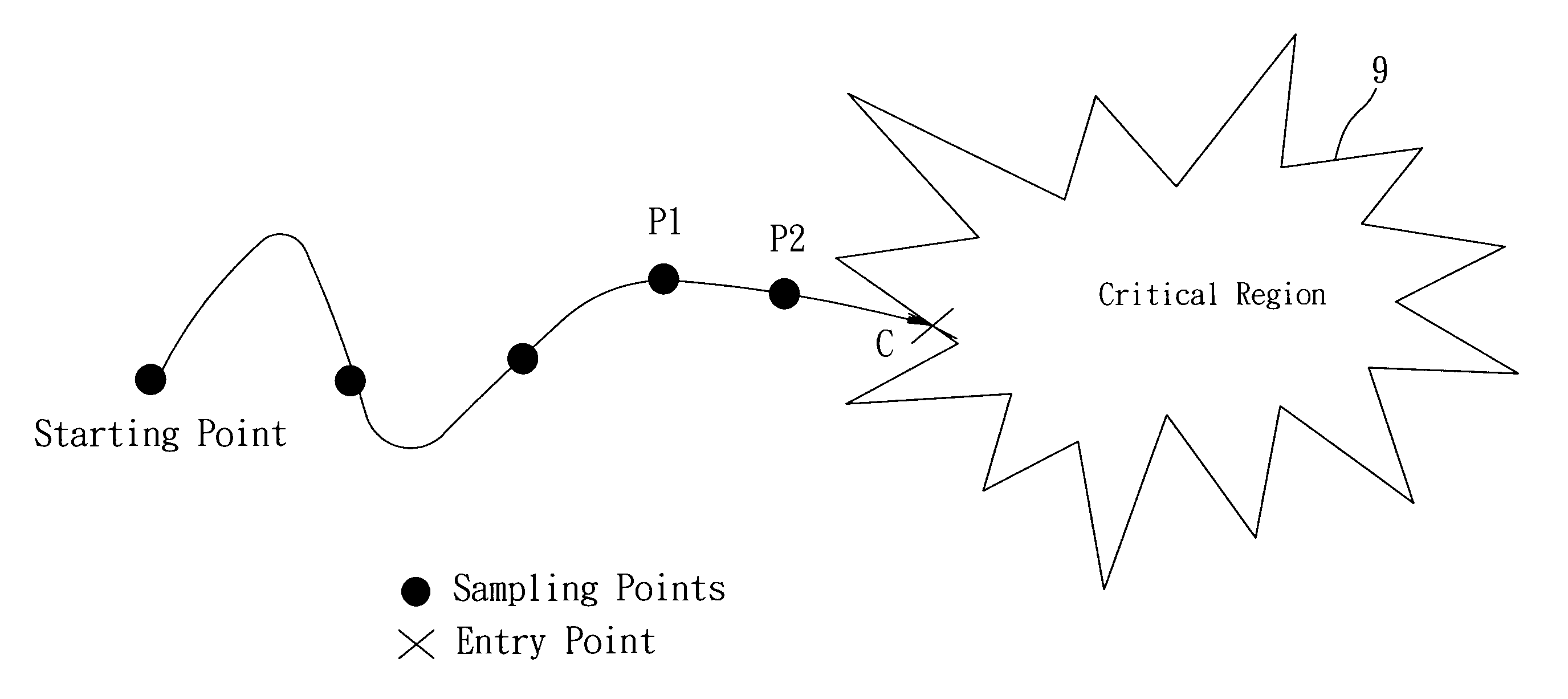
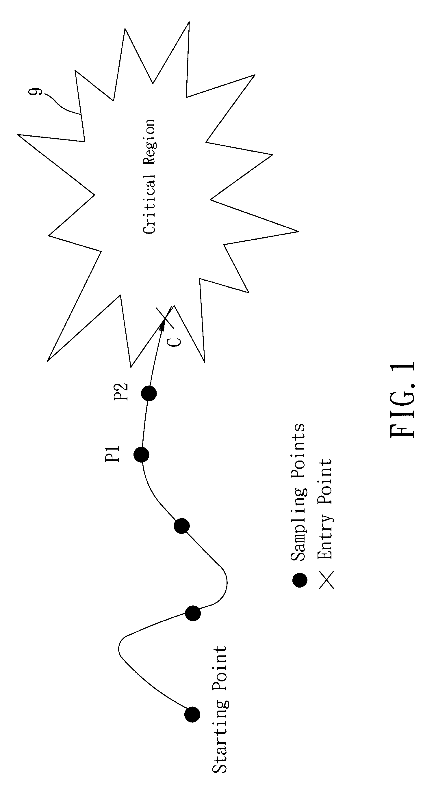
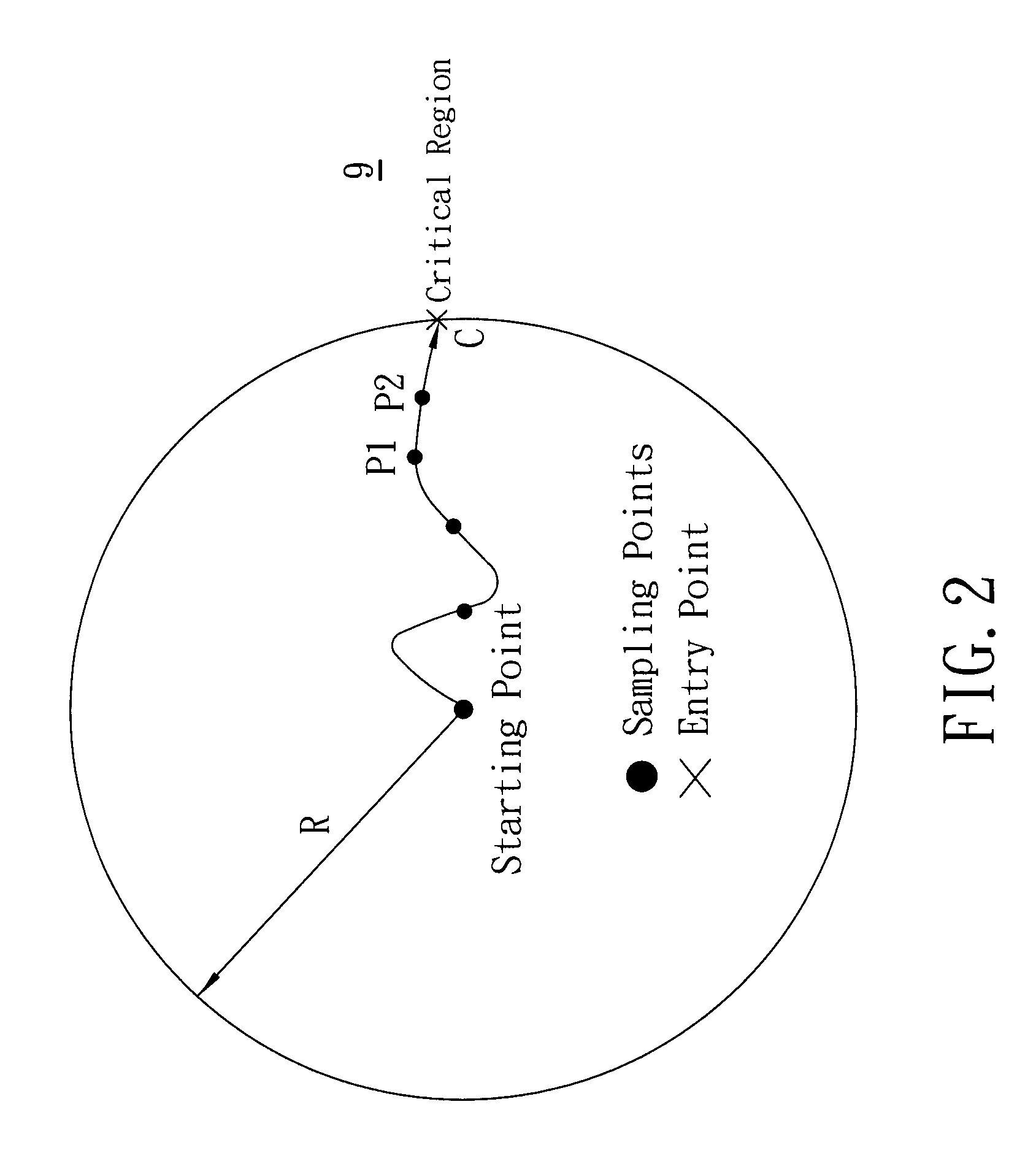
[0009]Therefore, the object of the present invention is to provide a method of reducing power consumption of a radio badge in a boundary detection localization system, in which the radio badge is carried by a tracked target, performs location sampling communication with an infrastructure component of the localization system at the start and end of sampling time intervals such that positions of the radio badge can be estimated, and is provided with an accelerometer.

Problems solved by technology

However, the energy consumption of the mobile units, which are attached to or carried by tracked targets and are typically small battery-powered tags or radio badges, is directly proportional to the sampling rate.
The problem with fixed-rate sampling is that while the sampling rate can be set high to provide real-time location information, when the target is far from the critical region where the requirement for timely service is not as high, a high sampling rate and the high power requirements associated therewith will be unnecessary.
This is particularly problematic for the mobile units.

Method used


Image

  • Method of reducing power consumption of a radio badge in a boundary detection localization system
  • Method of reducing power consumption of a radio badge in a boundary detection localization system
  • Method of reducing power consumption of a radio badge in a boundary detection localization system

Examples


Embodiment Construction

[0020]A method of reducing power consumption of a radio badge in a boundary detection localization system according to a preferred embodiment of the present invention is used to detect whether a tracked target carrying a radio badge has reached a boundary of a critical region. The radio badge performs location sampling communication with an infrastructure component of the boundary detection localization system in order to estimate positions of the radio badge.

[0021]In greater detail, the boundary detection localization system is radio frequency-based, and is composed of an infrastructure component and a mobile component. The infrastructure component includes a positioning engine, and beacon nodes installed on, for example, the ceiling of a deployed environment. These beacon nodes use radio to periodically broadcast beacon packets containing their beacon IDs. The mobile component includes the radio badge carried by the tracked target. The radio badge acquires a record of the receivin...


PUM


Abstract

A method of reducing power consumption of a radio badge in a boundary detection localization system is disclosed, in which the radio badge is carried by a tracked target and performs location sampling communication with an infrastructure component of the localization system at the start and end of sampling time intervals such that positions of the radio badge can be estimated. The method includes: determining a velocity of the radio badge; estimating a critical time for the radio badge to reach a critical region through division in which a critical distance from an estimated position obtained at the end of a most recent sampling time interval to the critical region is the dividend, and the velocity of the radio badge is the divisor; and controlling the radio badge to perform location sampling communication with the infrastructure component of the localization system at the end of the critical time.

Description

CROSS-REFERENCE TO RELATED APPLICATION[0001]This application claims priority of Taiwanese Application No. 097146751, filed on Dec. 2, 2008.BACKGROUND OF THE INVENTION[0002]1. Field of the Invention[0003]The present invention relates to an indoor localization method, more particularly to a method of reducing power consumption of a radio badge in a boundary detection localization system.[0004]2. Description of the Related Art[0005]Sensor network technologies have undergone significant advances in recent times. This has enabled a variety of applications in consumer electronics. For example, sensor networks are increasingly being used for asset tracking in warehouses, patient monitoring in medical facilities, using location to infer activities of daily living (ADL) at home, and other such object-tracking applications.[0006]One class of localization technology aims at detecting the crossing of boundaries. For example, boundary detection localization may be used for detection of troop mov...

Claims


Application Information

Patent Timeline
Patent Type & Authority Patents(United States)
IPC IPC(8): G08B13/14
CPCG08B21/0261G08B21/0275G08B21/22
Inventor HUANG, POLLYLIN, TSUNG-HANCHU, HAO-HUA
Owner NAT TAIWAN UNIV
Learn More