Implant location positioning system

Active Publication Date: 2012-03-06
BURGKART RAINER
View PDF12 Cites 28 Cited by
  • Summary
  • Abstract
  • Description
  • Claims
  • Application Information

AI Technical Summary

Benefits of technology

[0028]a navigation system for tracking the position of the device relative to the position of the bone that includes a computer-aided control unit that is adapted to calculate and virtually merge in a spatially correct manner implant parts with image or geometric data of the bone, wherein the calculation is based on navigational data of the trackable device and on data input of planned corrective measures, wherein the computer-aided control unit is further adapted to, after data input of the planned corrective measures, with the aid of corresponding calculation algorithms, and as a function of the position of the device on the accessible bone surface, virtually merge the corresponding position of the second section of the implant with the referenced image or geometric data of the bone, wherein the computer aided control unit is still further adapted to calculate the position of the second section of the implant geometrically offset to take into account a correction equal to the geometry of the planned geometric shift.
[0029]The present invention also uses the conventional navigation system as basis, but for the planning a virtual implant is not shifted virtually in the control unit, but rather a specially tracked device is. This device carries in it all the geometric characteristics of the original implant necessary for the planning as characteristics, and is shifted on the real bone in the surgical field.
[0030]The preparatory steps before use of the device according t

Problems solved by technology

This task represents a special technical challenge for the operator.
However, in order to hammer in this hole, it is necessary that the bone not yet be separated, because otherwise the first bone section would deviate during the procedure with the chisel since it cannot be held in a fixed manner yet, but is only surrounded by muscle and fatty tissue, which does not provide any hold when the chisel is struck into the bone.
It is understandable that these circumstances frequently lead to sub-optimal implant positions, so that either an attempt is made to “compensate” for it by a slight correction—as planned and needed—and/or there is an increased risk of delayed bone healing and loosening of the implant and thus the necessity of repeated surgery(ies).
The exact performance of such an operation is very difficult technically and so far depended greatly—mo

Method used


Image

  • Implant location positioning system
  • Implant location positioning system
  • Implant location positioning system

Examples


Embodiment Construction

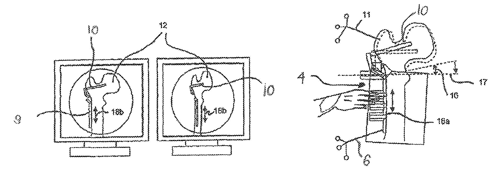
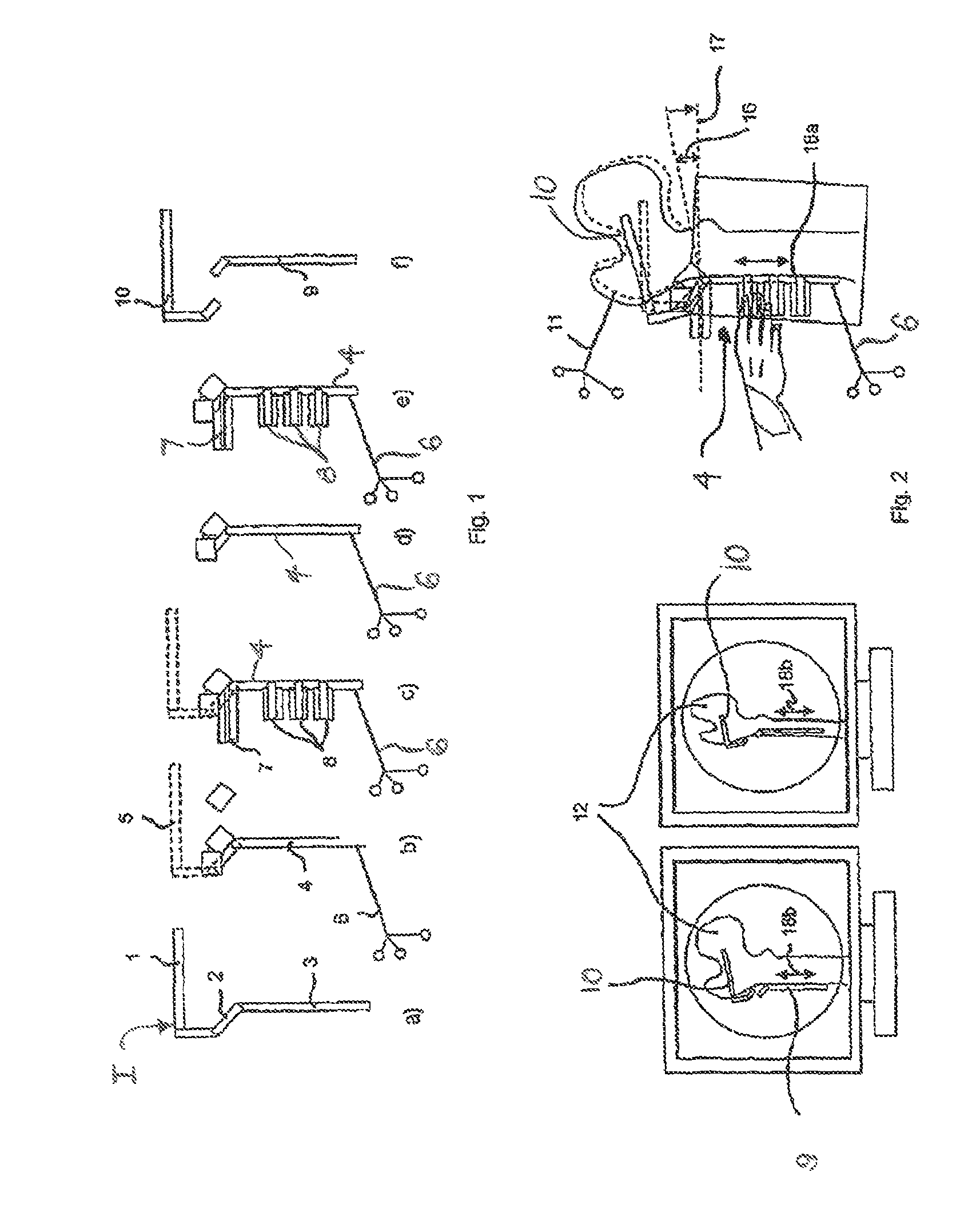
[0038]In FIG. 1a, in the side view a typical implant I to be used is shown: a “right angle plate”, using a schematic representation. Hereby this consists of a blade part 1, which is driven into the bone, a right-angle bend 2 (because of the anatomy—trochanter major) and a plate-part 3, which must be flush with the bone surface. The simplest form of the device is shown in FIG. 1b for the sake of understanding the device according to the invention (solid part without dotted line) and shows that the device 4 consists only of the plate part, which has a form and dimensions identical to the original plate part 3, and, for example, of a small part of the right angle bend 2 (in any case only parts that lie outside the bone). Such implants I are frequently rounded at the bone contact surface in order to correspond to the bone geometry better, which is mostly round. The device 4 always has an identical geometry. For the sake of understanding, part of the entire implant I that is not containe...


PUM


Abstract

The invention relates to an implant layer positioning system comprising a device that can be fixed to a bone section and is used to plan the positioning of implants in order to enable corrective operations to be performed on the bone with optimum bone contact. Said device reproduces the geometry of at least one section of the implant and can be freely oriented by the operator towards accessible parts of the bone. The inventive system also comprises a control unit which virtually evaluates the relevant implant parts, on the basis of the navigation data of the tracked device and the data input of the planned corrective operation, in the form of three-dimensional geometry bodies in fluoroscopy sketches or other referenced image or geometry data. Once the planned proceedings have been inputted, the control unit of the navigation system can virtually merge the corresponding position of all implant parts with the referenced image or geometry data of the patient in a three-dimensional manner by means of corresponding computational algorithms, and once the device has been oriented, the control unit can store the position of said device with all related dependent positions of the implant parts planned at the same time, and all of the planning information can be made available for use with navigated tools.

Description

BACKGROUND[0001]The introduction of osteosynthesis material or implants for secure attachment of two bone fragments to one another—independently of whether they occurred as a result of a traumatic fracture or were caused iatrogenically by targeted intraoperative separation of a bone (osteotomy)—is a frequent task in accident surgery and orthopedics.[0002]This task represents a special technical challenge for the operator. For example, in the not infrequently necessary surgical correction of incorrect positioning of bones, an iatrogenic separation of the bone with the removal of a correcting wedge is usually necessary. Depending on the procedure, in the case of many osteosynthesis implants (for example angle plate for the upper thigh bone near the hip joint), the anchoring of an implant must be prepared ahead of time before separation of the bone in the bone that will later be a fragment, using a bone blade chisel [Müller 1984, Burgkart 2005]. As long as the bone is intact and as a r...

Claims


Application Information

Patent Timeline
IPC IPC(8): A61B5/00
CPCA61B17/152A61B17/1703A61B17/1725A61B17/1732A61B17/809A61B2019/5238A61B2019/5483A61B17/8095A61B2090/376A61B2090/3983Y10S128/92Y10S623/914
Inventor BURGKART, RAINER
Owner BURGKART RAINER
Why Eureka
Try Eureka