Method of arc ion plating and target for use therein

a technology of arc ion plating and target, which is applied in the direction of electrolysis components, vacuum evaporation coatings, coatings, etc., can solve the problems of poor production efficiency complicated manufacturing process of rod target b>52/b>, so as to reduce the target manufacturing cost, improve the yield of target materials, and uniform film thickness distribution

Inactive Publication Date: 2012-03-13
KOBE STEEL LTD
View PDF4 Cites 6 Cited by
  • Summary
  • Abstract
  • Description
  • Claims
  • Application Information

AI Technical Summary

Benefits of technology

[0015]Accordingly, it is an object of the present invention to provide an arc ion plating method and a target used therein, which are not only capable of obtaining a uniform film thickness distribution substantially throughout the overall length of a work but also capable of improving the yield of the target material and reducing the target manufacturing cost in comparison with the related art.
[0016]For achieving the above-mentioned object, in the arc ion plating method according to the present invention there are included a step of disposing a target and a work within a vacuum chamber and a step of evaporating and ionizing the target by vacuum arc discharge to produce target material ions and conducting the target material ions to the work to form a film on the work. In the film forming step, an arc spot position on the target surface is controlled so as to make the consuming speed (evaporation quantity per unit time) of both longitudinal end portions of the target higher than the consuming speed of a central portion of the target. This control makes it possible to obtain a uniform film thickness distribution substantially throughout the overall length of the work.
[0017]Further, in the arc ion plating method according to the present invention, as the target there is disposed one whose at least both longitudinal end portions and the other central portion can be divided from each other, and the formation of a film involving changing the consuming speed as referred to above is performed. In this case, until at least the central portion of the target reaches a consumption limit, only both longitudinal end portions higher in consumption speed are replaced. Such a partial replacement makes it possible for the mutually separable components of the target to be all used up to the consumption limit. This permits decreasing the amount of the target material used relative to an effective consumption quantity of the target regardless of shapes of the target and thereby improving the yield of the target material. This makes it possible to reduce the target manufacturing cost and the price of the target and hence reduce the price of the film-formed product obtained.

Problems solved by technology

However, the conventional arc ion plating method described above is disadvantageous in that the production efficiency of the rod target 52 is poor.
This makes the manufacturing process for the rod target 52 complicated.

Method used


Image

  • Method of arc ion plating and target for use therein
  • Method of arc ion plating and target for use therein
  • Method of arc ion plating and target for use therein

Examples


example

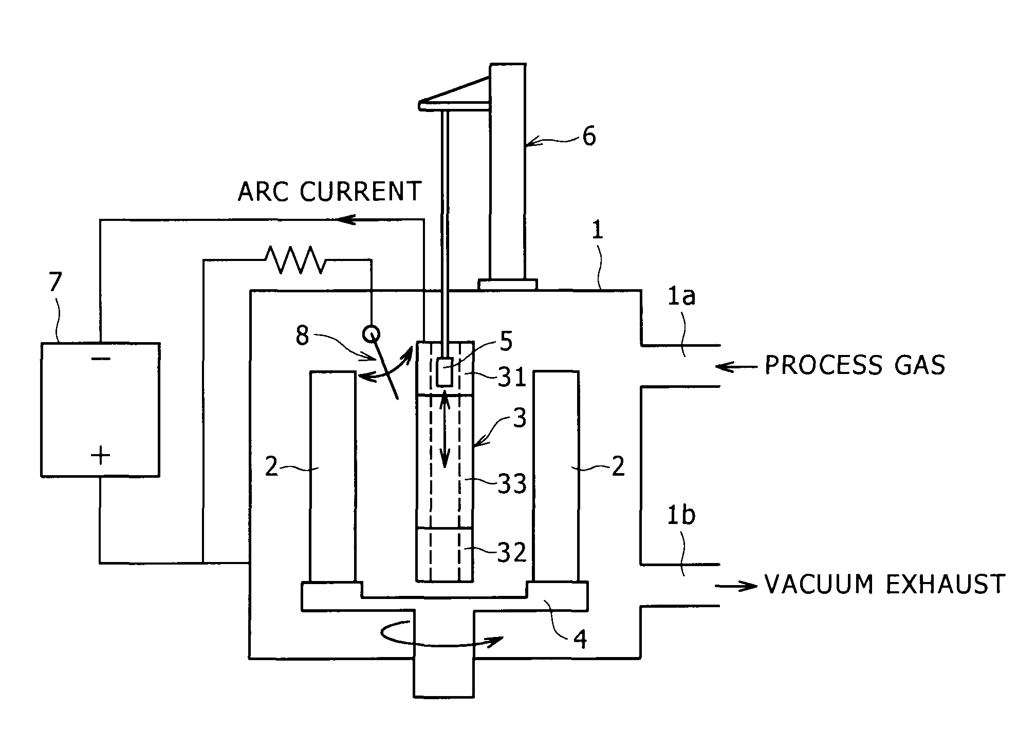
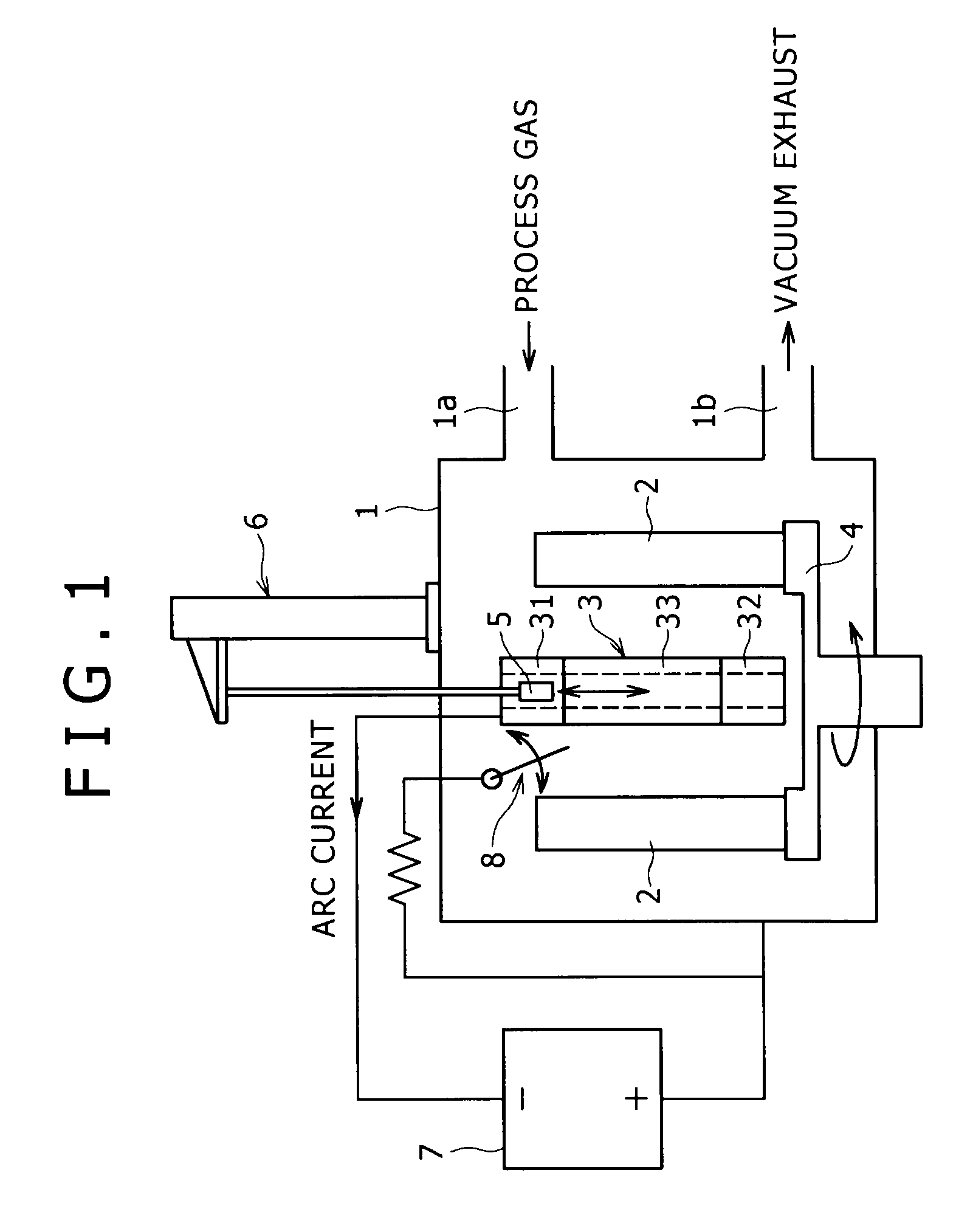
[0059]Using the apparatus shown in FIG. 1, arc ion plating was performed in a working example of the present invention and also in a comparative example (the related art disclosed in Japanese Patent Laid-Open Publication No. 2004-107750).

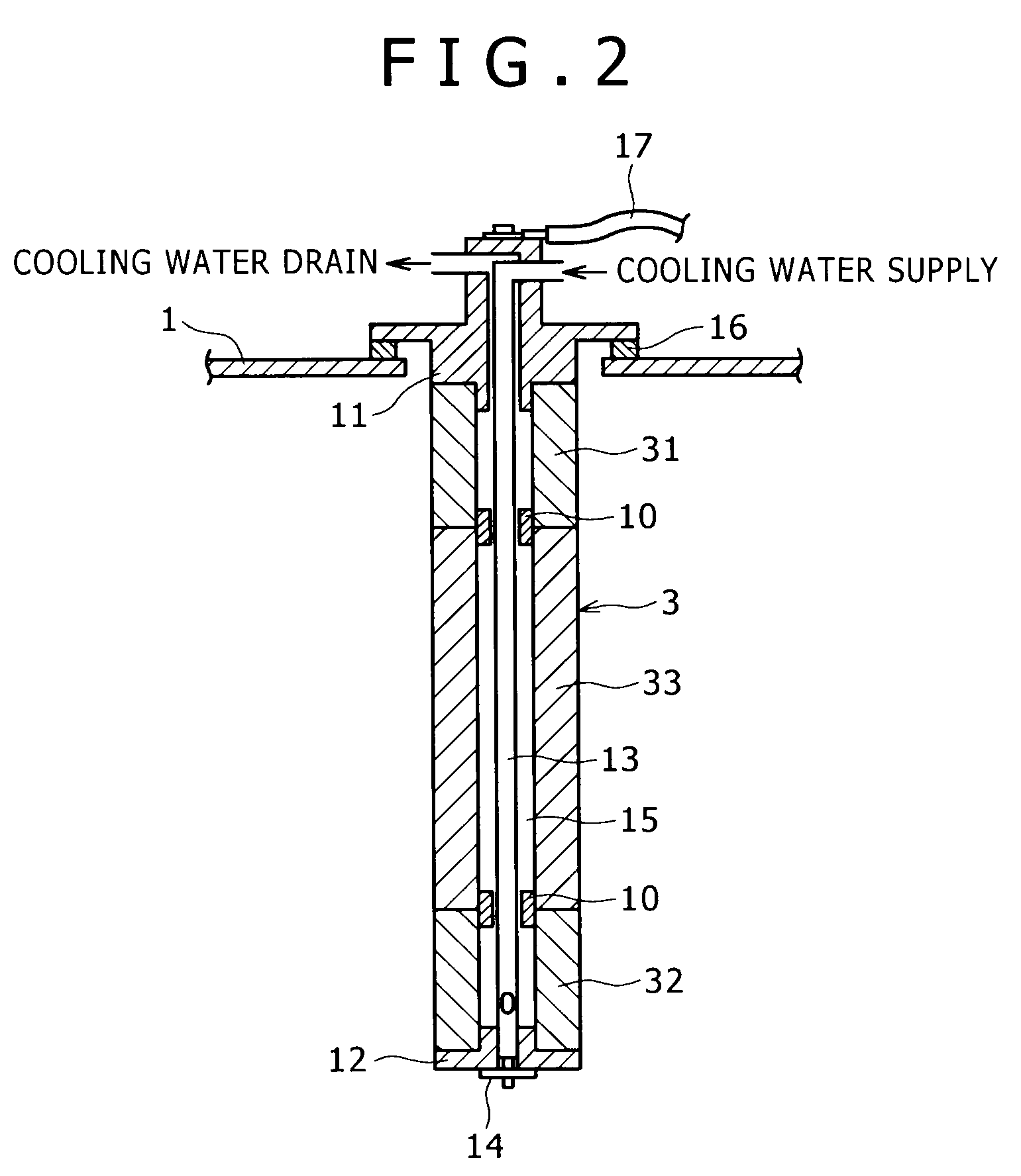
[0060]The work 2 was cylindrical and having an outside diameter of 90 mm and a length L of 500 mm. The target 3 used in the working example was in the shape of a cylinder having an overall length of 700 mm. Upper and lower targets 31, 32 constituting both end portions were each 130 mm in outside diameter, 50 mm in inside diameter and 150 mm in length, while a central target 33 constituting a central portion was 130 mm in outside diameter, 50 mm in inside diameter and 400 mm in length. A consumption limit corresponded to an outside diameter of 70 mm. The target used in the comparative example was in the shape of a cylinder of 700 mm in overall length and having stepped portions. In the comparative target, both end portions were each 130 mm in outside...


PUM

PropertyMeasurementUnit
lengthaaaaaaaaaa
lengthaaaaaaaaaa
diameteraaaaaaaaaa

Abstract

In an arc ion plating method, the target is divided into a central portion and longitudinal end portions at both longitudinal ends of the central portion. A constituent material of the target is evaporated and ionized by vacuum arc discharge using the target as a cathode, wherein the position of an arc spot on a surface of the target is controlled such that the consuming speed of the longitudinal end portions becomes higher than that of the central portion, whereby at least one of the longitudinal end portions will reach its consumption limit before the target central portion reaches its consumption limit. Only the respective longitudinal end portion that has reached its consumption limit is thereafter replaced, and the film forming step is continued.

Description

FIELD OF ART[0001]The present invention relates to an arc ion plating method for forming a hard film on cutting tools and mechanical parts (sliding parts) for the improvement of abrasion resistance, as well as a target used in the method.BACKGROUND ART[0002]Arc ion plating is known as a method for forming a film on a work. In the arc ion plating, vacuum arc discharge is performed in a vacuum atmosphere using a target as a cathode, the target being formed of a material to be evaporated for forming a film. This discharge causes the target material to be evaporated and ionized. The resulting target material ions are conducted to a work and form a film on the work. For forming a hard film of a metal nitride or a metal carbide by the arc ion plating there is performed reactive coating in which a reactive gas is introduced into a vacuum chamber, e.g., such reactive coating as introducing N2 gas to a target formed of Cr to form a CrN film.[0003]As an example of a conventional arc ion plati...

Claims


Application Information

Patent Timeline
Patent Type & Authority Patents(United States)
IPC IPC(8): C23C14/34
CPCC23C14/325C23C14/3407H01J37/32055H01J37/32614C23C14/351H01J37/34
Inventor FUJII, HIROFUMI
Owner KOBE STEEL LTD
Why Eureka
Try Eureka