Battery pack with cell-level fusing

a battery pack and cell-level technology, applied in the field of batteries, can solve the problems of increasing affecting affecting the reliability of the system, so as to improve the performance of the battery pack, the risk of sustained arcing of the predetermined interconnect is minimized, and the effect of complexity, weight and siz

Active Publication Date: 2012-03-13
TESLA INC
View PDF9 Cites 5 Cited by
  • Summary
  • Abstract
  • Description
  • Claims
  • Application Information

AI Technical Summary

Benefits of technology

[0006]The present invention provides a battery pack, or battery pack module, that achieves improved battery pack performance, system reliability and system safety while impacting only a small region of the battery pack / battery module, and thus having only a minor impact on battery pack cost, complexity, weight and size. The battery pack / battery module is designed such that the fusible interconnects associated with a single battery, or a specific fusible interconnect associated with a single battery, will be the last interconnect(s) to fuse during a short circuit event. The risk of sustained arcing for the predetermined interconnect(s) is minimized through the use of rapid clearing interconnects. As a result, the risk of damage and excessive heating is also minimized.

Problems solved by technology

If the arc is not quickly extinguished, for example by containment, cooling, insufficient voltage / current, etc., the intense heat generated by the arc may damage, if not combust, nearby materials and components.
It is more difficult, however, to control unintended circuit interruptions that nevertheless may occur due to an inadvertent abusive situation (e.g., tool dropped on a battery pack; battery pack dropped; car crash which causes damage to the battery pack, etc.).
If the temperature of these adjacent cells is allowed to increase unimpeded, they may also enter into a state of thermal runaway, leading to a cascading effect that may propagate throughout the entire battery pack.
As a result, not only is power from the battery pack interrupted, but the system employing the battery pack is more likely to incur extensive collateral damage due to the scale of thermal runaway and the associated release of thermal energy.
This approach, however, leads to increased cost, complexity and weight, all of which may be quite significant in large battery packs such as those employed in hybrid and all-electric vehicles.

Method used


Image

  • Battery pack with cell-level fusing
  • Battery pack with cell-level fusing
  • Battery pack with cell-level fusing

Examples


Embodiment Construction

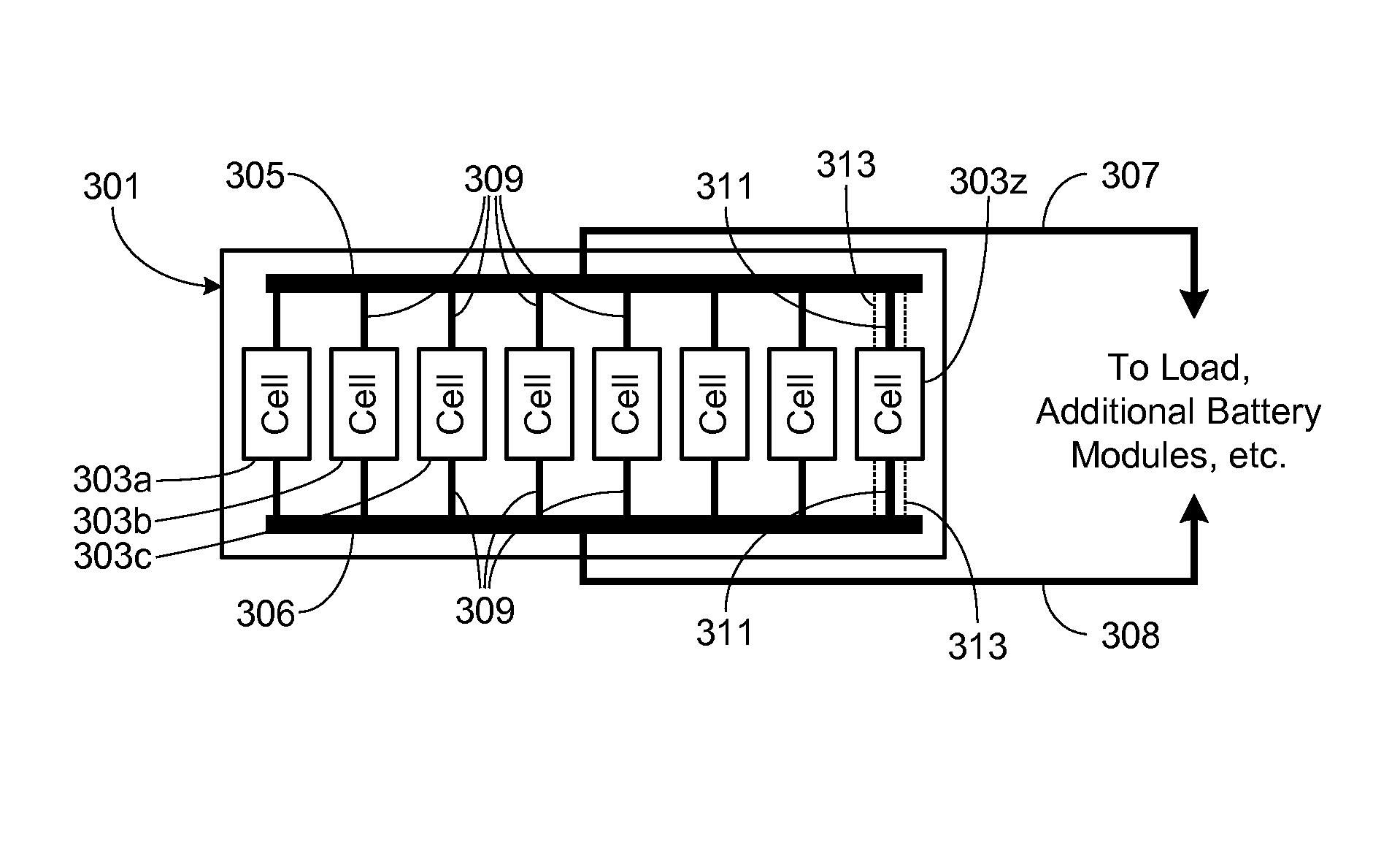
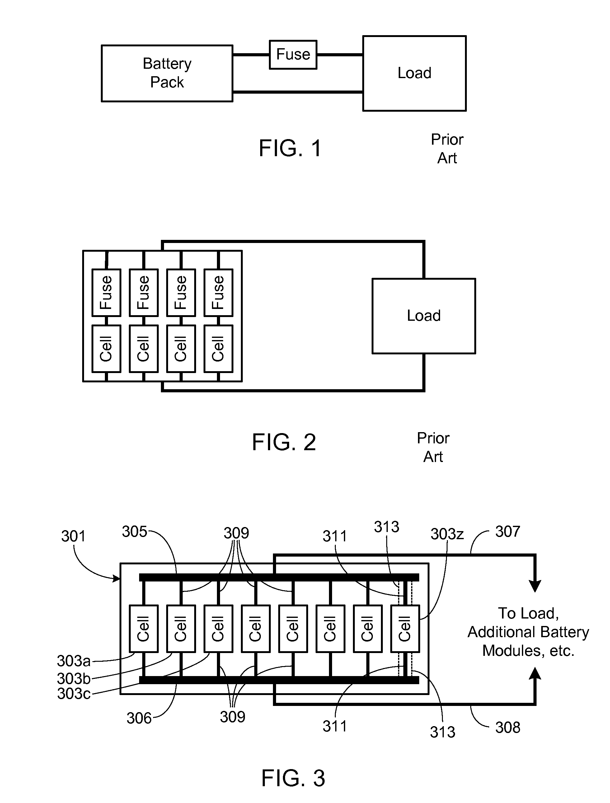
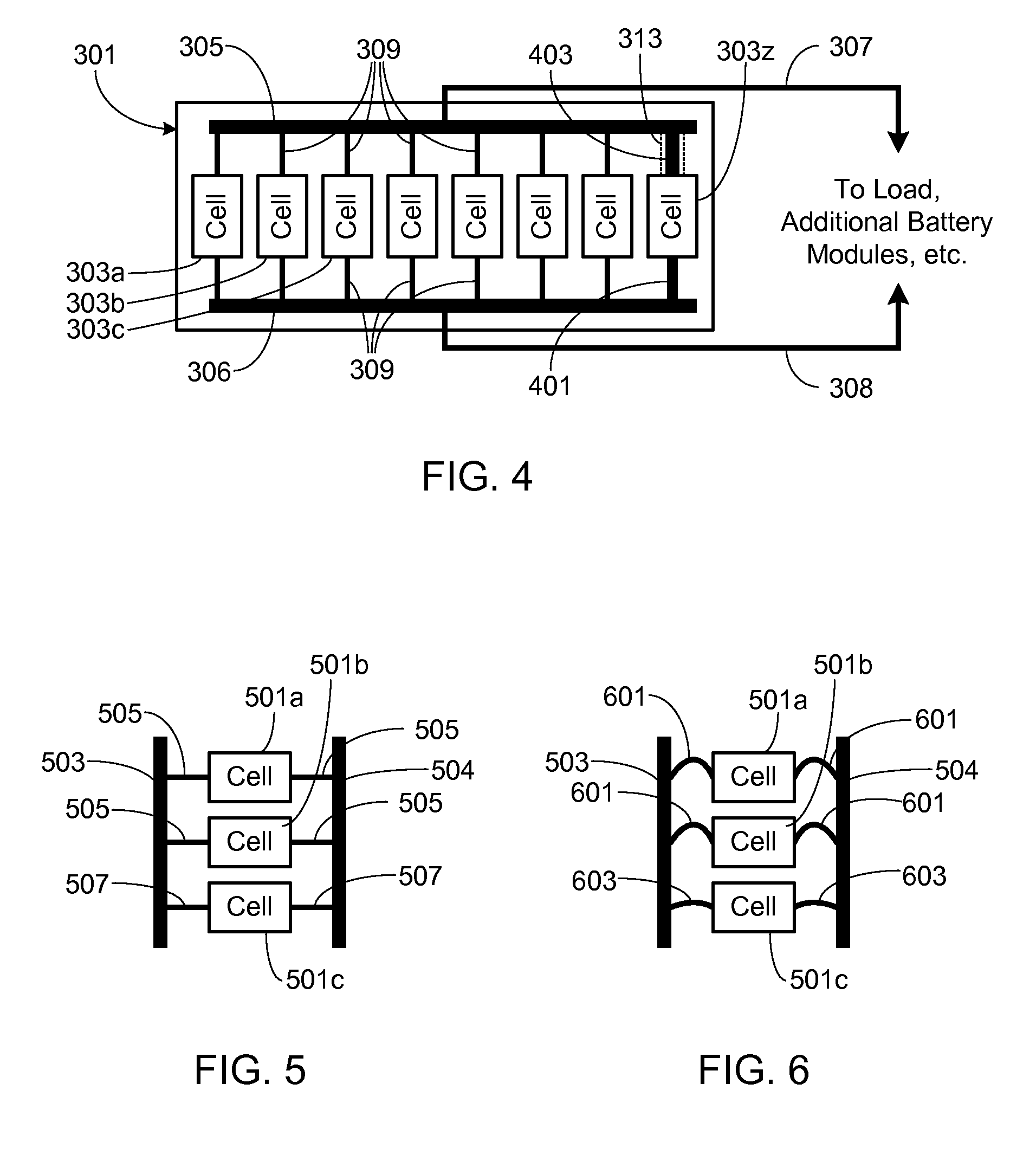
[0032]In the following text, the terms “battery”, “cell”, and “battery cell” may be used interchangeably and may refer to any of a variety of different cell types, chemistries and configurations including, but not limited to, lithium ion (e.g., lithium iron phosphate, lithium cobalt oxide, other lithium metal oxides, etc.), lithium ion polymer, nickel metal hydride, nickel cadmium, nickel hydrogen, nickel zinc, silver zinc, or other battery type / configuration. The term “battery pack” as used herein refers to multiple individual batteries contained within a single piece or multi-piece housing, the individual batteries electrically interconnected to achieve the desired voltage and capacity for a particular application. The terms “electrical impedance” and “impedance” may be used interchangeably herein with both terms referring to the electrical impedance of the component in question. The term fusible interconnect as used herein refers to battery interconnect, typically a wire bond, th...


PUM

PropertyMeasurementUnit
temperatureaaaaaaaaaa
chargeaaaaaaaaaa
lengthaaaaaaaaaa

Abstract

A battery pack, or battery pack module, is provided that achieves improved battery pack performance, system reliability and system safety while impacting only a small region of the battery pack / battery module, and thus having only a minor impact on battery pack cost, complexity, weight and size. The battery pack / battery module is designed such that the fusible interconnects associated with a single battery, or a specific fusible interconnect associated with a single battery, will be the last interconnect(s) to fuse during a short circuit event. The risk of sustained arcing for the predetermined interconnect(s) is minimized through the use of rapid clearing interconnects. As a result, the risk of damage and excessive heating is also minimized.

Description

FIELD OF THE INVENTION[0001]The present invention relates generally to battery packs and, more particularly, to a battery pack that is designed to mitigate the effects of arcing during a short circuit.BACKGROUND OF THE INVENTION[0002]Arcing is a well-known phenomena that results when the current in an electrical circuit is interrupted, wherein an arc is formed across the newly created gap in the circuit. If the arc is not quickly extinguished, for example by containment, cooling, insufficient voltage / current, etc., the intense heat generated by the arc may damage, if not combust, nearby materials and components. Accordingly, special precautions must be taken in the design of switches, relays, fuses and circuit breakers that are intended for use in high-power circuits. It is more difficult, however, to control unintended circuit interruptions that nevertheless may occur due to an inadvertent abusive situation (e.g., tool dropped on a battery pack; battery pack dropped; car crash whic...

Claims


Application Information

Patent Timeline
Patent Type & Authority Patents(United States)
IPC IPC(8): H01M2/26H01M2/24H01M10/50H02J7/00H01M50/503H01M50/512H01M50/529H01M50/583H01M50/588
CPCH01M10/4264H01M2200/103H01M2200/106Y02E60/10H01M50/588H01M50/583H01M50/512H01M50/503
Inventor HERMANN, WESTON ARTHURKOHN, SCOTT IRAKREINER, PAUL BRYANGADDA, CHRISTOPHER DAVID
Owner TESLA INC
Why Eureka
Try Eureka