
Automatic amplitude control for voltage controlled oscillator

a voltage control and automatic technology, applied in the field of electronic circuits, can solve problems such as degrading the tuning range of oscillators

Active Publication Date: 2012-03-13
ADVANCED MICRO DEVICES INC
View PDF6 Cites 8 Cited by
  • Summary
  • Abstract
  • Description
  • Claims
  • Application Information

AI Technical Summary

Benefits of technology

This approach allows for non-invasive monitoring and adjustment of the VCO output signal amplitude, avoiding loading issues and ensuring a stable tuning range while maintaining low noise resilience, thus enhancing the overall performance of the VCO.

Problems solved by technology

However, the amplitude cannot be excessive as the large amplitude swing will otherwise cause varactor capacitance averaging and consequently degrade the oscillator tuning range.

Method used


Image

  • Automatic amplitude control for voltage controlled oscillator
  • Automatic amplitude control for voltage controlled oscillator
  • Automatic amplitude control for voltage controlled oscillator

Examples


Embodiment Construction

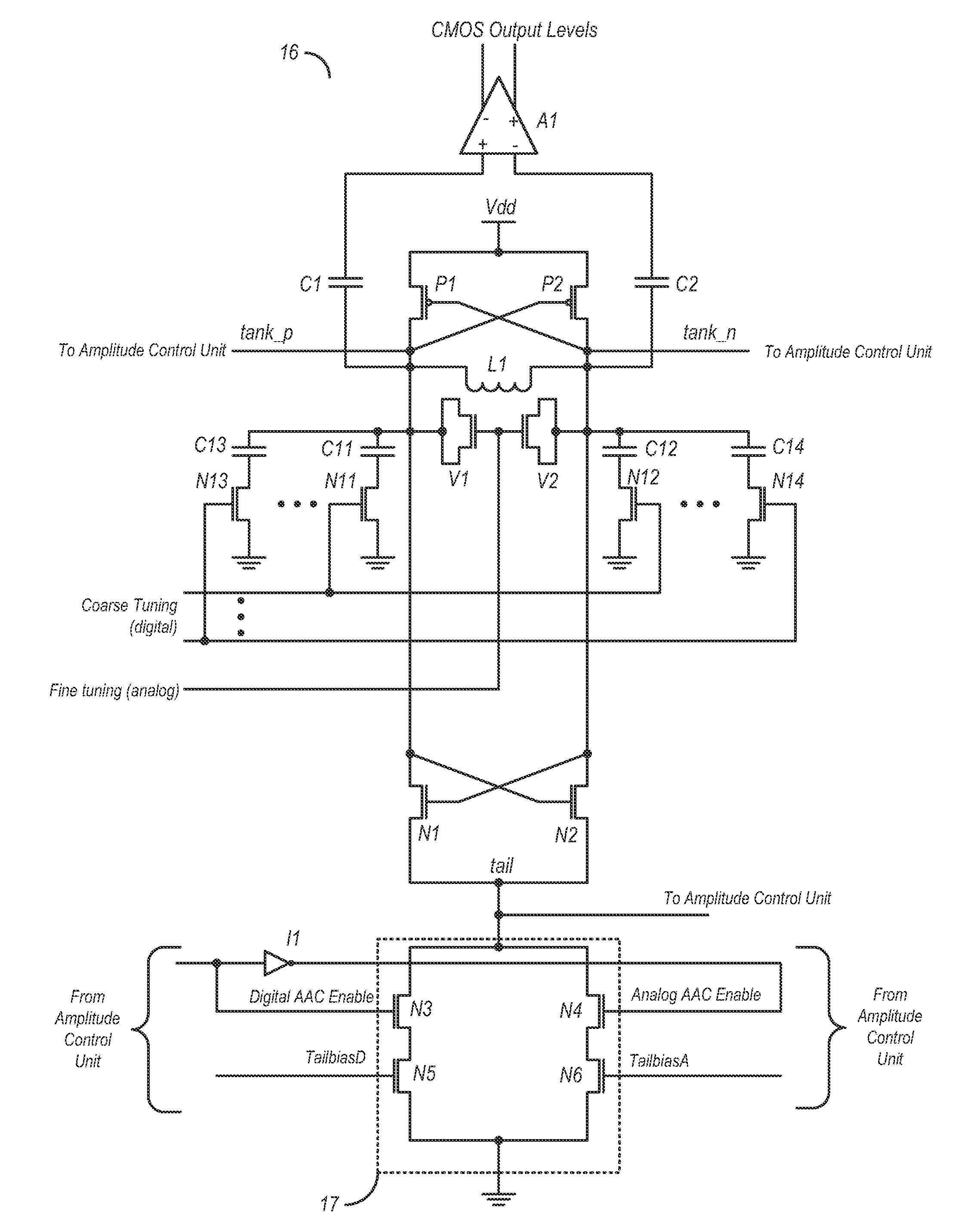
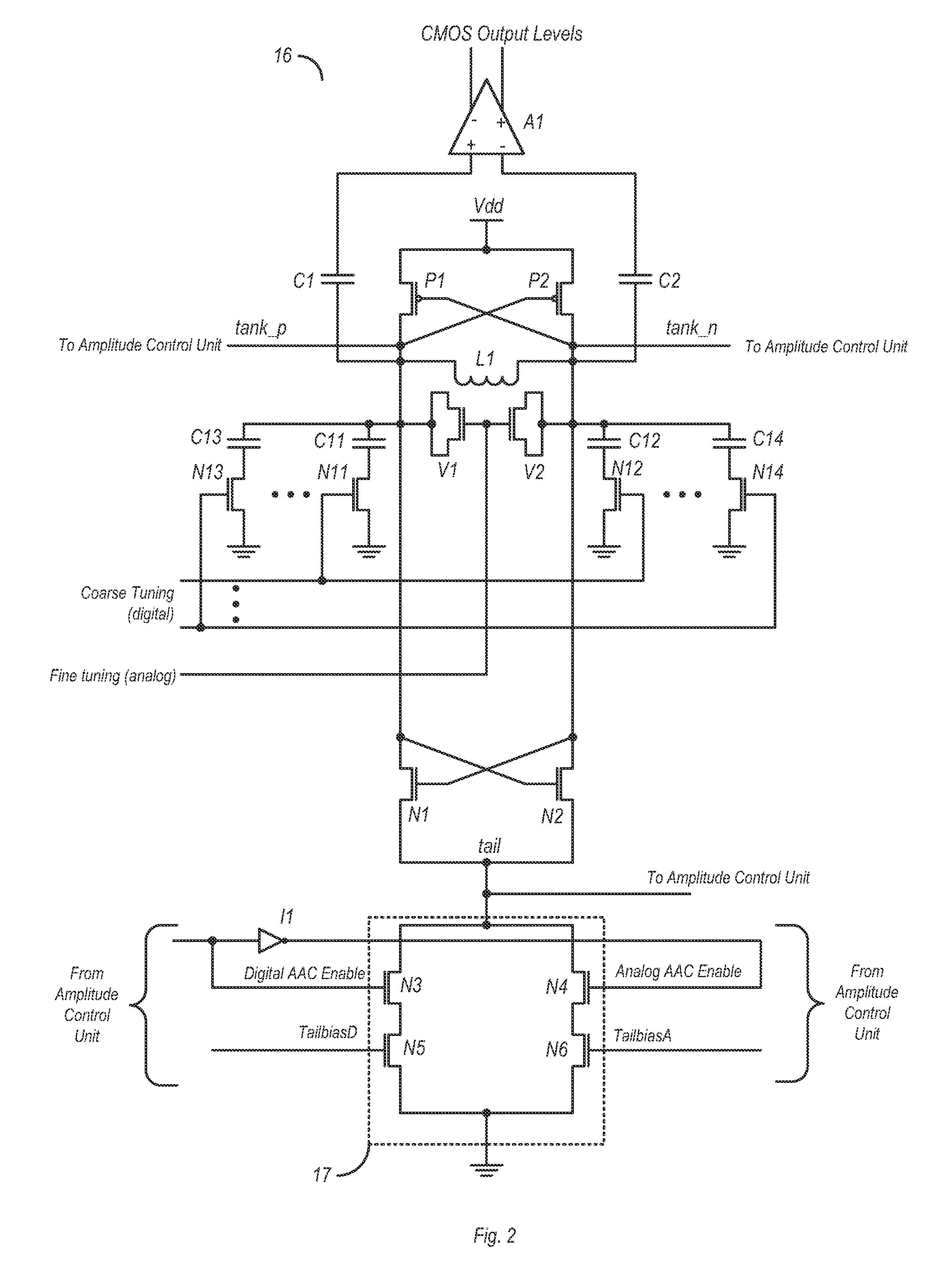
[0018]A method and apparatus for calibrating the amplitude of an output signal of a voltage-controlled oscillator (VCO) is described below by way of the examples in the drawings. The VCO may include an LC (inductive-capacitive) tank circuit. Monitoring of the output signal may be performed non-invasively by monitoring a tail node of the VCO instead of through a direct coupling to the LC tank circuit. By non-invasively monitoring the amplitude of the VCO output signal, problems such as loading (which can reduce the turning range of the LC tank circuit) may be avoided.

[0019]An amplitude control unit configured to calibrate the amplitude of the VCO output signal may determine its amplitude based on the voltage present on the tail node. Based on the tail node voltage and a target voltage, the amplitude control unit may determine whether or not the amplitude of the VCO output signal is within a specified range (e.g., if the tail node voltage exceeds the target voltage). If the amplitude ...


PUM


Abstract

A circuit and method for calibrating a VCO (voltage controlled oscillator) is disclosed. In one embodiment, a circuit includes a VCO and a bias control circuit coupled to a tail node of the VCO. An amplitude control unit may also be coupled to the tail node, wherein the amplitude control unit is configured to determine the amplitude of a VCO output signal based on a voltage present on the tail node. The amplitude control unit may also be configured to generate a bias voltage based on the amplitude of the VCO output signal and a target voltage. The bias control circuit may be coupled to receive the bias voltage from the amplitude control unit and may be further configured to adjust the voltage on the tail node based on the received bias voltage.

Description

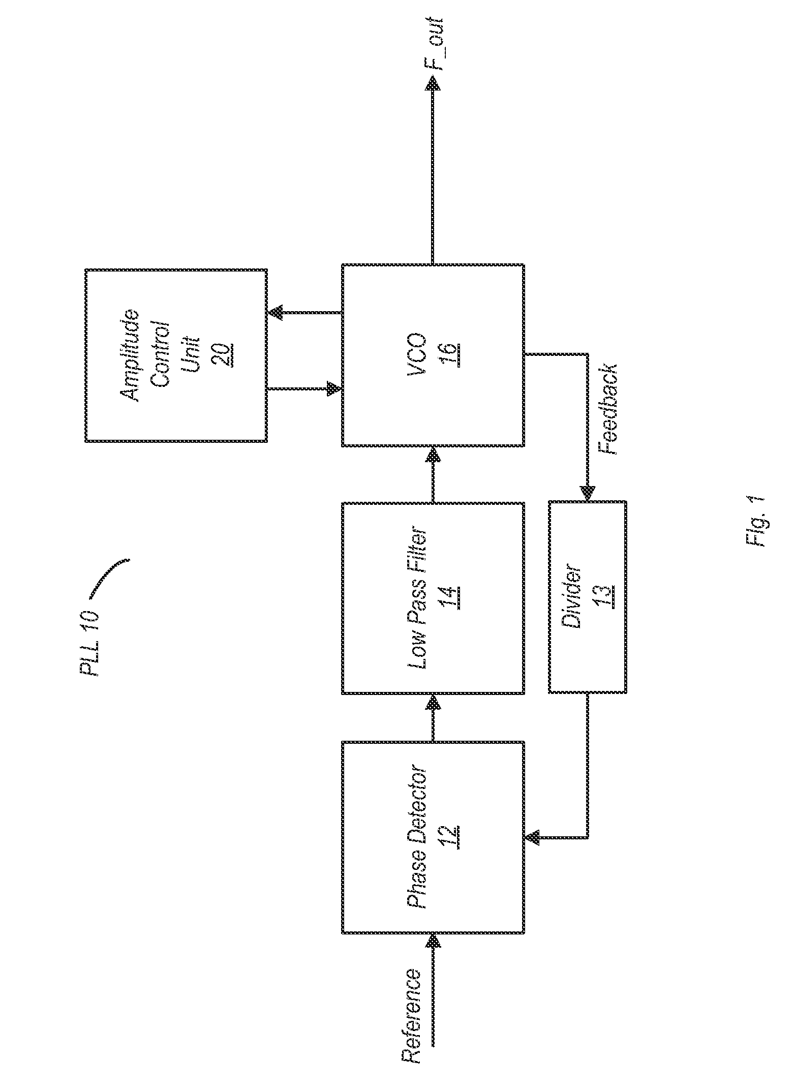
BACKGROUND[0001]1. Field of the Invention[0002]This invention relates to electronic circuits, and more particularly, to voltage controlled oscillators (VCOs).[0003]2. Description of the Related Art[0004]Phase-locked loops (PLLs) are commonly used for the generation of oscillating signals in a wide variety of electronic circuits. For example, PLLs may be used in digital circuits for clock generation and reproduction, in radio transmitter and receiver circuits for generation of signals at radio frequencies, and so forth.[0005]A typical PLL includes a phase detector coupled to receive a reference signal, a low pass filter coupled to the output of the phase detector, and a voltage controlled oscillator (VCO). The output of the VCO may provide the output signal of the PLL, and may also be fed back to an input of the phase detector via a feedback loop. In some instances, the output of the VCO may be divided before being provided to the phase detector. The phase detector is configured to c...

Claims


Application Information

Patent Timeline
Patent Type & Authority Patents(United States)
IPC IPC(8): H03B5/12H03L5/00
CPCH03L5/00H03L7/099H03L7/10
Inventor CHIANG, MEEI-LINGFISCHETTE, DENNIS M.LOKE, ALVIN LENG SUNOSHIMA, MICHAEL M.
Owner ADVANCED MICRO DEVICES INC
Learn More