Amplifier circuit

a technology of amplifier circuit and power supply, applied in the direction of amplifier details, amplifier with semiconductor device/discharge tube, differential amplifier, etc., can solve the problems of relatively poor power supply rejection ratio (psrr), relatively severe unwanted effects on output signals, and unwanted convolution of signals, so as to achieve the effect of greatly improving the power supply rejection ratio

Inactive Publication Date: 2006-06-27
INTEL MOBILE COMM GMBH
View PDF8 Cites 50 Cited by
  • Summary
  • Abstract
  • Description
  • Claims
  • Application Information

AI Technical Summary

Benefits of technology

[0012]The present invention is directed to an amplifier circuit which operates on the basis of the class D principle and has an improved power supply rejection ratio.
[0016]In accordance with yet another embodiment of the invention, the transfer function for the output voltage in relation to the supply voltage in consideration of the low-level signal response is ideally 0, in practical terms at least very low, which means that the power supply rejection ratio PSRR is greatly improved.
[0017]The quotient of the supply voltage and the amplitude voltage of the periodic signal is always constant in one example of the present invention. However, this quotient also describes the low-level signal gain, in particular, of the circuit, and the circuit described accordingly always operates at constant gain such that an additional advantage is that no convolution with a harmonic signal component of the supply voltage may arise.
[0020]So that the frequency of the periodic signal always remains constant despite the amplitude of the signal being linked to a possibly fluctuating supply voltage, there is advantageously provided a phase locked loop which ensures that the signal generator's frequency is constant.

Problems solved by technology

However, such amplifiers have relatively poor properties in terms of the power supply rejection ratio (PSRR).
Accordingly, fluctuations in the supply voltage or radio-frequency interference components in the supply voltage result in relatively severe unwanted effects on the output signal from the amplifier circuit.
A further problem of the principle described is the unwanted convolution of signals.
The problem is of great significance particularly because the interference may be at frequencies below the cut-off frequency of the low-pass filter at the output and is therefore not filtered out.
This increases the power consumption, however.
This severely reduces the efficiency of the amplifier, however.

Method used


Image

  • Amplifier circuit
  • Amplifier circuit
  • Amplifier circuit

Examples


Embodiment Construction

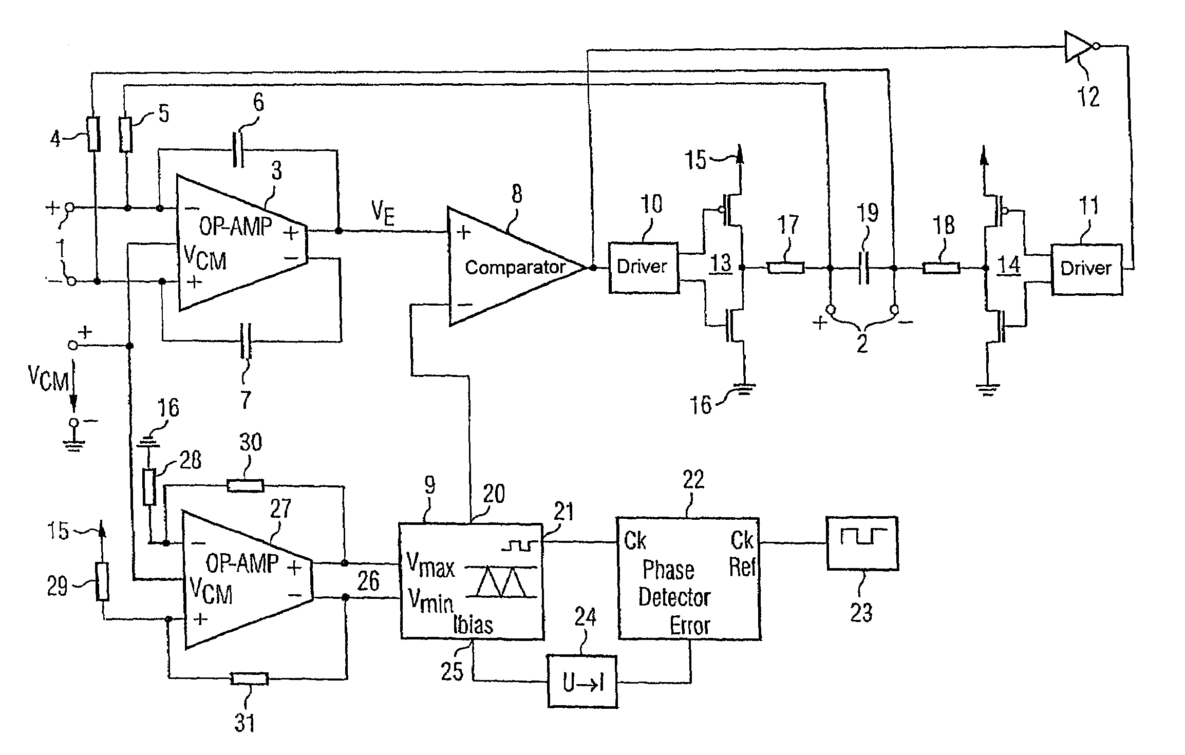
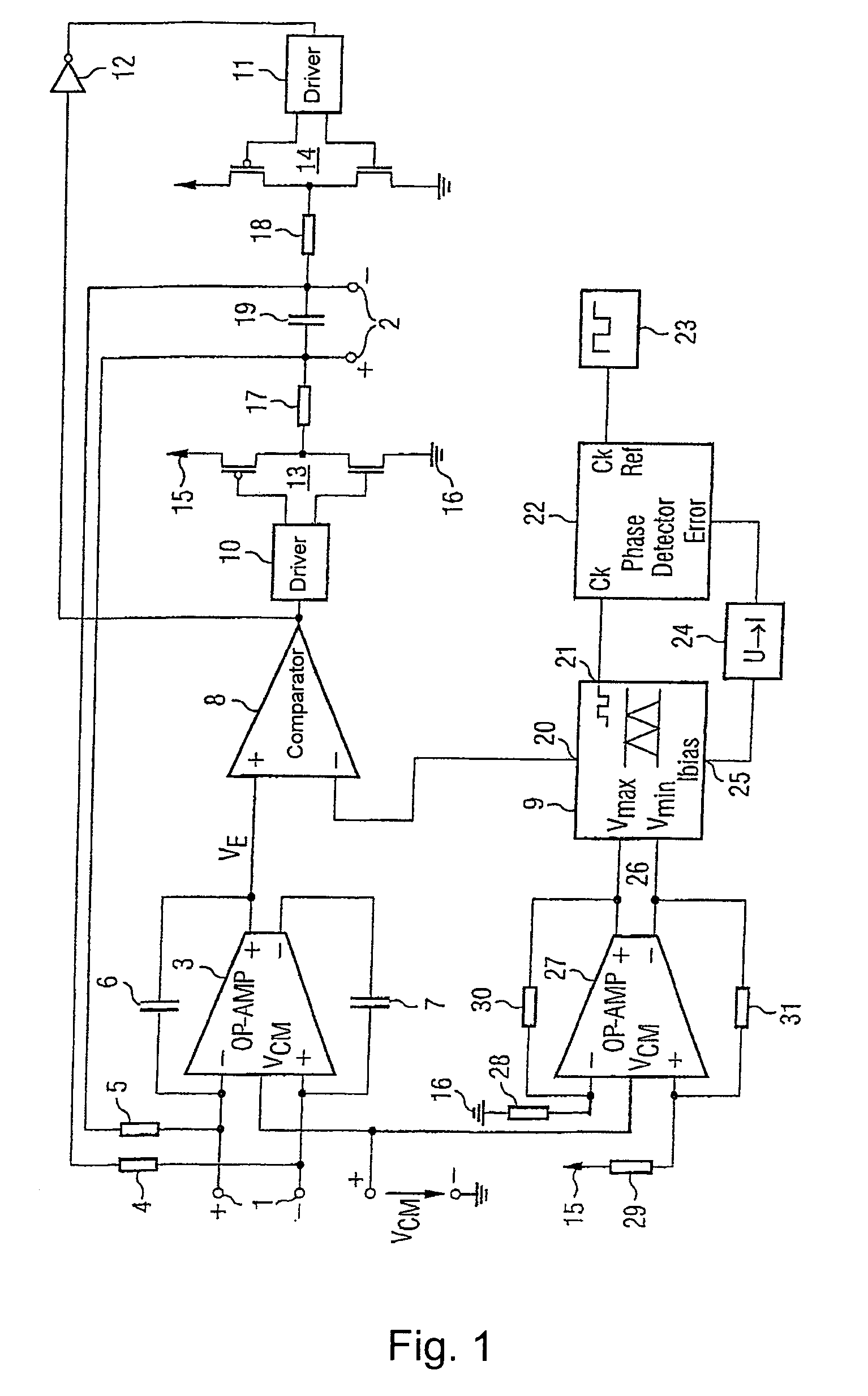
[0026]FIG. 1 shows an amplifier circuit based on the present invention using a block diagram. This circuit comprises an input 1 for supplying a useful signal to be amplified which is in the form of a symmetrical input with a pair of differential input terminals. The signal amplified using the present amplifier circuit, which signal is derived from the signal applied to the input 1, can be tapped off at the output 2, which is likewise symmetrically in the form of a pair of output terminals.

[0027]The input 1 has an amplifier 3 connected to it which forms a differential signal from the signal difference between the signal applied to the input 1 and the signal provided at the output 2. This differential signal is provided at the symmetrical input of the operational amplifier 3. For this, the pair of output terminals 2 is connected to the input of the amplifier 3 via a respective resistor 4, 5. In addition, the two output terminals of the operational amplifier 3 are connected to the two ...


PUM


Abstract

The invention is directed to an amplifier circuit based on the principle of a class D amplifier. To avoid unwanted convolution effects and to improve the power supply rejection ratio, provision is made for the amplitude of the ramp signal used for pulse width modulation to track proportionally the supply voltage for the amplifier circuit. For this purpose, the ramp signal generator has an amplitude control input suitably connected to supply and reference potentials. This ensures a constant duty ratio which is independent of the supply voltage. The present circuit may be used, for example, as a DC / DC converter or as an audio amplifier.

Description

REFERENCE TO RELATED APPLICATION[0001]This application is a continuation of PCT / DE03 / 02304, filed Jul. 9, 2003 which was not published in English, that claims the benefit of the priority date of German Patent Application No. DE 102 31 183.8, filed on Jul. 10, 2002, the contents of which are herein incorporated by reference in their entirety.FIELD OF THE INVENTION[0002]The present invention relates to an amplifier circuit.BACKGROUND OF THE INVENTION[0003]Audio signals are normally amplified using class D amplifiers, inter alia. In line with the underlying principle, a reference signal is first compared with a signal fed back from the output and a corresponding error signal is output. This signal is processed on a pulse width modulation basis using a sawtooth signal and is passed to an output amplifier stage. In this case, the output stage is operated so as to switch at a particular duty ratio. To maintain a flow of current at the output, a freewheeling diode and an inductor are provi...

Claims


Application Information

Patent Timeline
Patent Type & Authority Patents(United States)
IPC IPC(8): H03F1/02H03F3/195H03F3/217H03F3/38H03F3/45
CPCH03F3/195H03F3/2173H03F3/45475H03F2203/45078H03F2200/351
Inventor BERNARDON, DEREK
Owner INTEL MOBILE COMM GMBH
Why Eureka
Try Eureka